Material suction mold of automobile air inlet valve half-gear product and material suction hole machining technology of material suction mold

A technology of air intake valve and processing technology, which is applied to home appliances, other home appliances, household components, etc., can solve the problems of unqualified products, hidden safety hazards, and difficult processing of suction holes, etc., and achieves simple structure and real-time monitoring. Cavity pressure, the effect of preventing accidental falling off

Pending Publication Date: 2018-11-23
英瑟泰科精密注塑(苏州)有限公司
View PDF0 Cites 0 Cited by
  • Summary
  • Abstract
  • Description
  • Claims
  • Application Information

AI Technical Summary

Problems solved by technology

[0002] The mold of the traditional semi-tooth product of the automobile air intake valve has the following disadvantages: the main body of the plastic part is equipped with a metal insert and an aluminum cursor. Potential safety hazards lead to unqualified products. There are suction holes on the existing mold, but the diameter of the suction hole is large. If the insert falls off accidentally, the suction hole will be blocked by plastic. The mold needs to be repaired by the lower mold, so the mold needs to be repaired. To achieve anti-shedding and anti-clogging, it is generally possible to adopt a method with a smaller aperture, but the suction hole with a smaller aperture is difficult to process. Based on the above defects and deficiencies, it is necessary to improve the existing technology

Method used


Image

  • Material suction mold of automobile air inlet valve half-gear product and material suction hole machining technology of material suction mold
  • Material suction mold of automobile air inlet valve half-gear product and material suction hole machining technology of material suction mold
  • Material suction mold of automobile air inlet valve half-gear product and material suction hole machining technology of material suction mold

Examples


Embodiment Construction

[0019] The preferred embodiments of the present invention will be described in detail below in conjunction with the accompanying drawings, so that the advantages and features of the invention can be more easily understood by those skilled in the art, so as to define the protection scope of the present invention more clearly.

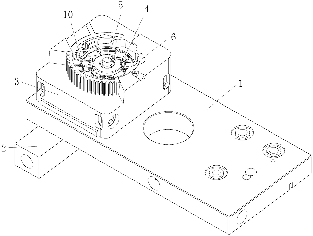
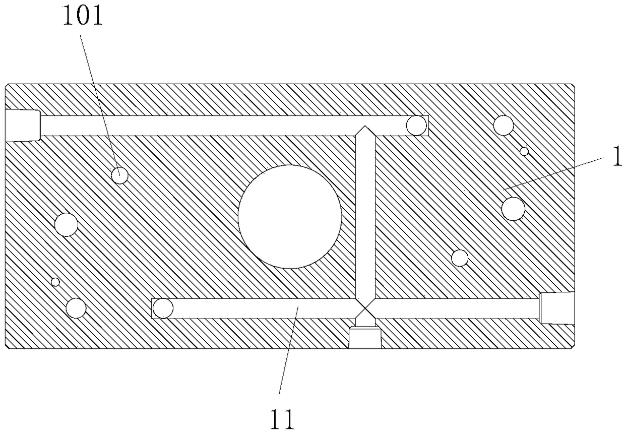
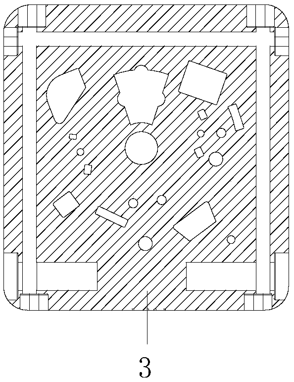
[0020] see Figure 1 to Figure 5 , the embodiment of the present invention includes:

[0021] A suction mold for a semi-tooth product of an automobile air intake valve and a process for processing the suction hole thereof. The suction mold for a semi-tooth product of an automobile air intake valve includes a backing plate 1, a connecting block 2, a mold core 3, and a suction component 4 , a metal insert positioning component 5, a plastic main body positioning insert 6 and a pressure sensor 7, a connecting block 2 is provided at the lower part of the backing plate 1, a mold core 3 is installed on the backing plate 1, and a suction core 3 is inserted into ...


PUM


Abstract

The invention discloses a material suction mold of an automobile air inlet valve half-gear product and a material suction hole machining technology of the material suction mold. The material suction mold of the automobile air inlet valve half-gear product comprises a base plate, a connecting block, a mold core, a material suction assembly, a metal insert positioning assembly, a plastic part body positioning insert and a pressure sensor. The connecting block is arranged at the lower part of the base plate, the mold core is arranged on the upper plane of the base plate, and the material suctionassembly, the metal insert positioning assembly and the plastic part body positioning insert are inserted in the mold core. A metal insert sleeves a fixed column of the metal insert positioning assembly, and an optical label aluminum sheet is arranged on the upper part of the material suction assembly. A mold cavity is formed in the upper end face of the mold core, and a plastic part body is arranged in the mold cavity. The plastic part body positioning insert is used for positioning a plastic part body, a pressure sensor is further inserted into the mold core, and the pressure sensor is usedfor detecting the pressure of the mold cavity. In this way, the mold is simple in structure and capable of positioning products; insert products can be prevented from accidentally falling off; and thepressure of the mold cavity can be monitored in real time.

Description

technical field [0001] The invention relates to the technical field of industrial machinery, in particular to a suction mold for a semi-tooth product of an automobile intake valve and a processing technology for a suction hole thereof. Background technique [0002] The mold of the traditional semi-tooth product of the automobile intake valve has the following disadvantages: the main body of the plastic part is equipped with a metal insert and an aluminum cursor. Potential safety hazards lead to unqualified products. There are suction holes on the existing mold, but the diameter of the suction hole is large. If the insert falls off accidentally, the suction hole will be blocked by plastic. The mold needs to be repaired by the lower mold, so the mold needs to be repaired To achieve anti-shedding and anti-clogging, the method of smaller aperture can generally be adopted, but the suction hole with smaller aperture is difficult to process. Based on the above defects and deficienc...

Claims


Application Information

Patent Timeline
IPC IPC(8): B29C33/04B29C33/12B29C33/18B29C33/38
CPCB29C33/04B29C33/12B29C33/18B29C33/3842B29L2031/7506
Inventor 张义航
Owner 英瑟泰科精密注塑(苏州)有限公司
Why Eureka
Try Eureka