Automatic polishing machine

An automatic polishing and polishing head technology, which is applied in the direction of surface polishing machine tools, grinding/polishing equipment, grinding racks, etc., can solve the problem of difficulty in keeping the inclination of the jig consistent, difficulty in maintaining the uniformity of the polishing effect, and low efficiency. problem, to achieve the effect of simple structure, consistent inclination and excellent quality

Pending Publication Date: 2018-11-23
深圳市五力波智能科技有限公司
View PDF0 Cites 1 Cited by
  • Summary
  • Abstract
  • Description
  • Claims
  • Application Information

AI Technical Summary

Problems solved by technology

The tilting of existing jigs is mostly adjusted by jacking parts. When it is necessary to improve processing efficiency and tilt multiple jigs at the same time, if the original jacking parts adjustment method is still used, it is difficult to keep each jig The degree of inclination is consistent, and it is difficult to maintain the uniformity of the polishing effect between the workpieces, and the structure is complex and the efficiency is low

Method used


Image

  • Automatic polishing machine
  • Automatic polishing machine
  • Automatic polishing machine

Examples


Embodiment Construction

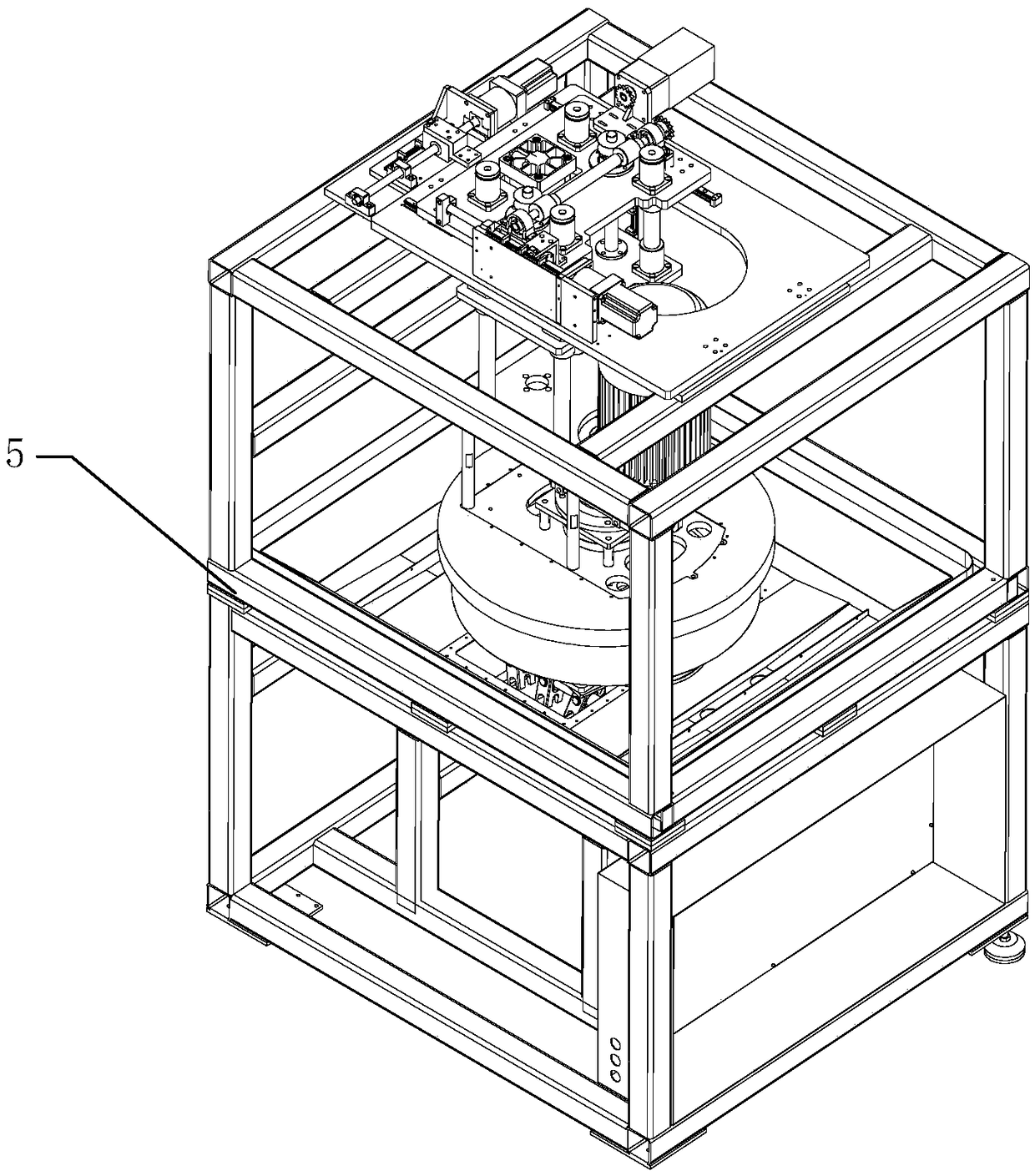
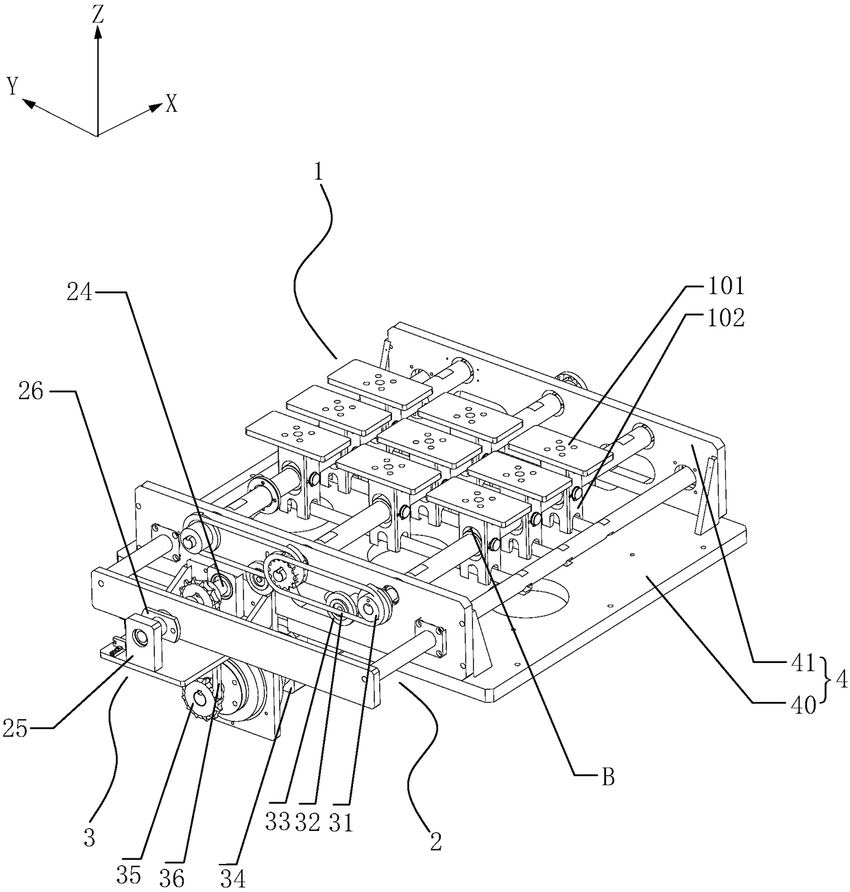
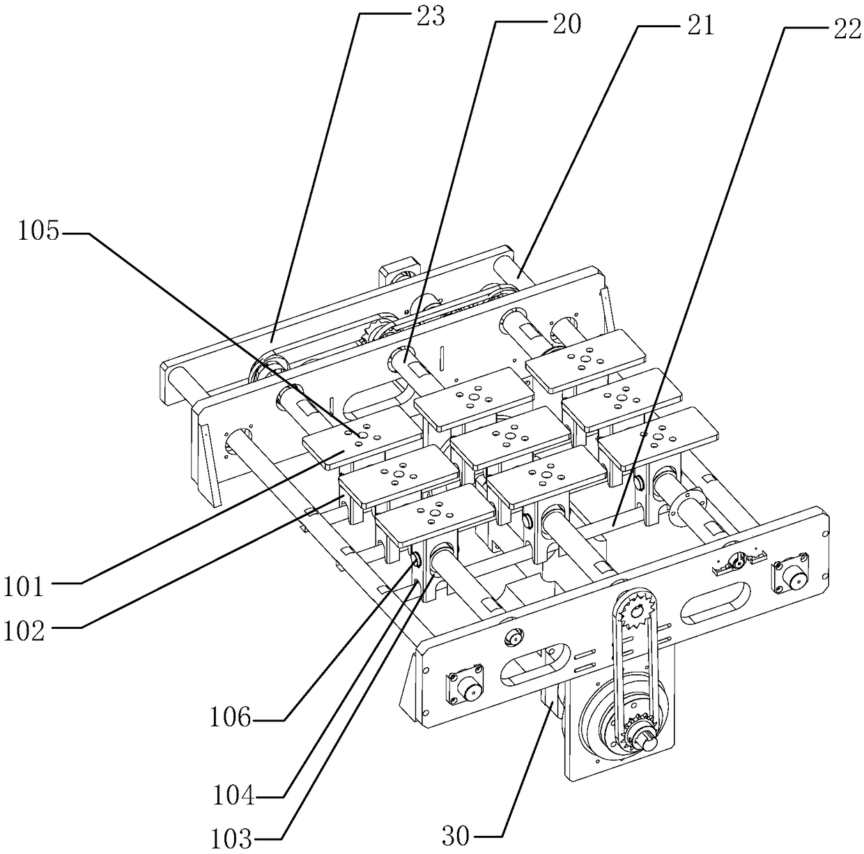
[0036] The idea, specific structure and technical effects of the present invention will be clearly and completely described below in conjunction with the embodiments and accompanying drawings, so as to fully understand the purpose, scheme and effect of the present invention. It should be noted that, in the case of no conflict, the embodiments in the present application and the features in the embodiments can be combined with each other.

[0037]It should be noted that, unless otherwise specified, when a feature is called "fixed" or "connected" to another feature, it can be directly fixed and connected to another feature, or indirectly fixed and connected to another feature. on a feature. In addition, descriptions such as up, down, left, and right used in the present invention are only relative to the mutual positional relationship of the components of the present invention in the drawings, unless otherwise specified.

[0038] Also, unless defined otherwise, all technical and ...


PUM


Abstract

The invention relates to an automatic polishing machine. The automatic polishing machine comprises a jig mechanism, a polishing component and a machine frame. In a jig component, a link rod componentcomprises a plurality of rotating shafts and connecting rods installed along an X-direction, and a plurality of translation shafts installed along a Y-direction. A positioning piece support frame of aplurality of jigs is provided with first through holes in the X-direction and second through holes in the Y-direction. A plurality of the jigs is arranged in an opposite row and/or column. While therotating shafts pass through one column of the first through holes, and are rotated around an own center shaft through the action of a rotating driving component, the jigs are driven to be rotated andinclined around the rotating shaft. While the translation shafts pass through one row of the second through holes and are fixedly connected with the connecting rod, and the connecting rods are horizontally moved along the X-direction through the action of a translation driving component, the jigs are driven to be rotated and inclined around a hinging piece installed in the Y-direction, and a workpiece is polished by a polishing head component above the workpiece in an inclined process. The above automatic polishing machine is simple in structure, and capable of adjusting the multiple jigs andenabling the jigs to be simultaneously inclined, wherein an inclined degree is consistent, so an arc chamfering edge or a cambered surface with good quality is obtained.

Description

technical field [0001] The invention relates to the field of polishing equipment, in particular to an automatic polishing machine. Background technique [0002] Most of the existing polishing machines are used to polish the plane of the workpiece, but as people have higher and higher requirements for the refinement and diversification of polished products, in addition to flat polishing, users have a demand for arc-shaped chamfering or arc-shaped polishing. Taking the glass screen of an electronic product as an example, when the edge of the glass screen is processed with a curved chamfering and polishing process, a more comfortable feel can be obtained and the appearance is more beautiful. [0003] In the traditional arc polishing, the method of flat sweeping is still used to process the arc chamfer or arc surface. The processing accuracy of the arc chamfer or arc surface obtained is not high, and it is easy to cause deformation. In order for the polishing head to accurately...

Claims


Application Information

Patent Timeline
Patent Type & Authority Applications(China)
IPC IPC(8): B24B29/02B24B41/02B24B41/06
CPCB24B29/02B24B41/02B24B41/06
Inventor 刘江张文斌
Owner 深圳市五力波智能科技有限公司
Why Eureka
Try Eureka