
Air supply pipe for air suction

A technology for air supply pipes and ventilation pipes, which can be used in respiratory protection devices, fire rescue, life-saving equipment, etc., and can solve problems such as development restrictions and expensive materials.

Inactive Publication Date: 2018-11-23
福州超高层消防科技有限公司
View PDF0 Cites 0 Cited by
  • Summary
  • Abstract
  • Description
  • Claims
  • Application Information

AI Technical Summary

Problems solved by technology

Its development is limited due to the high cost of its materials

Method used


Image

  • Air supply pipe for air suction
  • Air supply pipe for air suction
  • Air supply pipe for air suction

Examples


Embodiment Construction

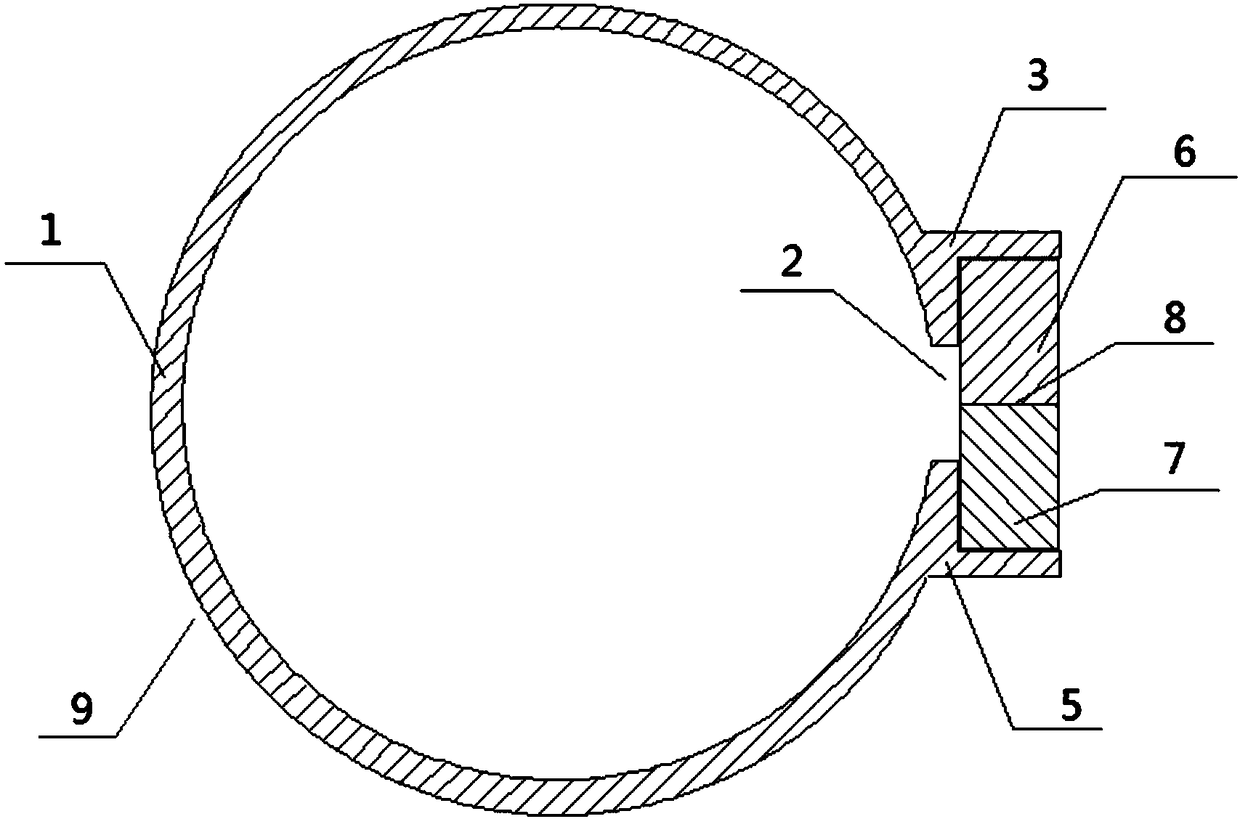
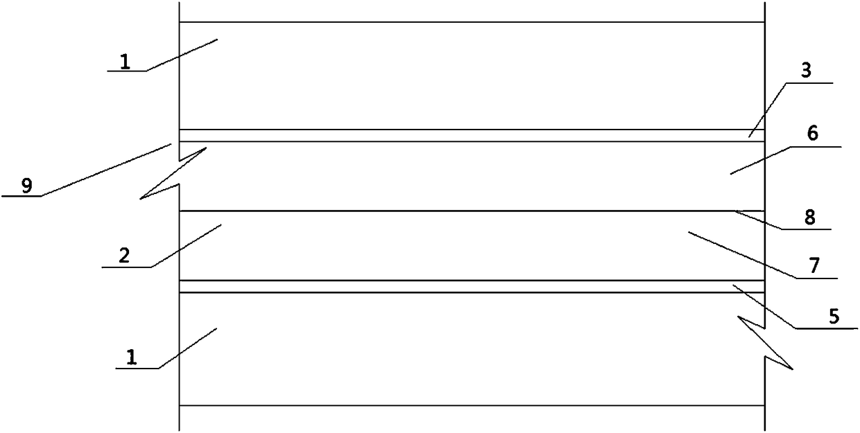
[0071] Such as figure 1 said, figure 1 It is a cross-sectional view of the air supply pipeline 9 of the first embodiment of the application. The pipe wall 1 of the air supply pipeline 9 of the first embodiment of the application is provided with an opening 2 along the hole direction of the air supply pipeline 9, and the above opening 2 runs through the pipe. Wall 1, the pipe wall 1 on one side of the above-mentioned opening 2 is provided with a strip-shaped L-shaped groove 3 for accommodating the sealing strip I6, and the pipe wall 1 on the other side of the above-mentioned opening 2 is provided with a strip-shaped groove 3 for accommodating the sealing strip II7. L-shaped groove 5, L-shaped groove 3 is connected with sealing strip I6 through adhesive, L-shaped groove 5 is connected with sealing strip II7 through adhesive, and sealing strip I6 and sealing strip II7 are magnetically attracted and relatively close together for sealing The function of the opening 2 is that the a...


PUM


Abstract

The invention discloses an air supply pipe for air suction. A linear opening in the hole direction of the air supply pipe is formed in the pipe wall of the air supply pipe; the pipe wall adopts a rigid material; the pipe walls on the two sides of the opening are connected with a sealing strip I and a sealing strip II separately; and the sealing strip I and the sealing strip II are connected together through magnetic attraction and can be moved to open the opening.

Description

technical field [0001] The present application relates to a gas supply pipeline. Background technique [0002] In building fires, smoke is the main cause of preventing people from escaping and causing the death of trapped people. When a fire breaks out in a building, in order to avoid the damage of smoke to people, the prior art is as follows: an air supply pipeline is arranged inside or outside the structure of the building, and the above-mentioned air supply pipeline is provided with an air outlet at a suitable position on the floor. The air inlet of the air supply pipeline extends to the outside of the building to communicate with the gas outside the building. The air supply pipeline extends downwards and then extends a certain distance to the outside of the building. After adopting the above technical solution, escaped people can Open the valve or switch to inhale the air through the air outlet, because the air inlet of the air supply pipeline is arranged on the outside...

Claims


Application Information

Patent Timeline
Patent Type & Authority Applications(China)
IPC IPC(8): A62B7/00
CPCA62B7/00
Inventor 不公告发明人
Owner 福州超高层消防科技有限公司
Learn More