A method, device and electronic device for determining the relationship between a point and a fence
A fence and relationship technology, applied in the field of data processing, can solve problems such as low algorithm efficiency, avoid erroneous conclusions and improve the efficiency of determination
- Summary
- Abstract
- Description
- Claims
- Application Information
AI Technical Summary
Problems solved by technology
Method used
Image
Examples
Embodiment 1
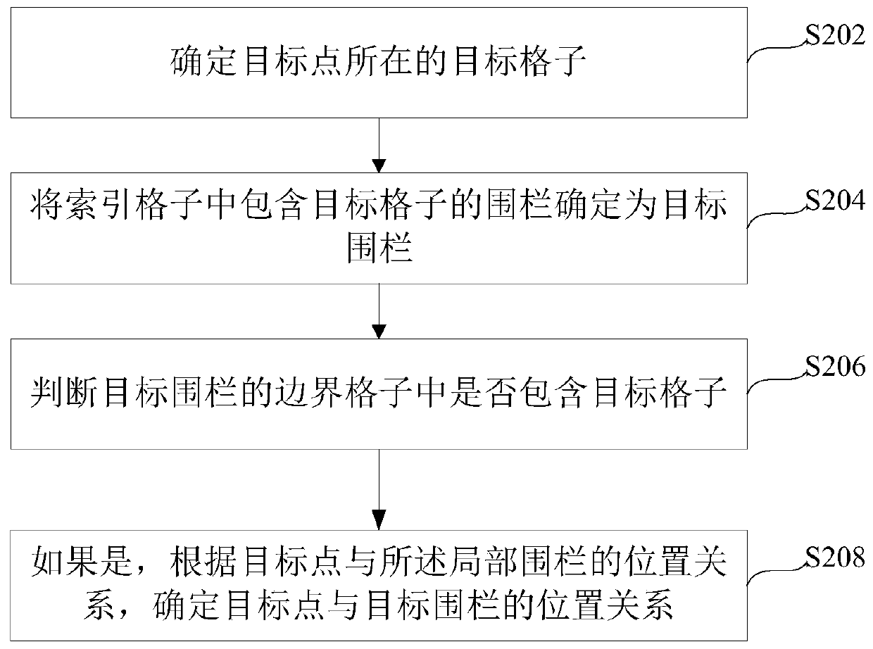
[0054] see figure 2 A flow chart of a method for determining the relationship between a point and a fence is shown, the method can be applied to a device supporting the global discrete grid system DGGS, and the positional relationship between the fences of target points can be determined through the device.
[0055] figure 2 The shown method for determining the relationship between a point and a fence is applied to a device supporting the global discrete grid system DGGS, and the method includes the following steps:
[0056] Step S202, determining the target grid where the target point is located; wherein, grid is an abbreviation of hexagonal grid.
[0057] In this embodiment, the target point is the user's location, for example, the longitude and latitude coordinates of the user's location. If the method for determining the relationship between the point and the fence provided by the embodiment of the present invention is applied to the taxi-hailing software, then the loc...
Embodiment 2
[0141] see Figure 4 A flow diagram of the first method of optionally determining the point-to-fence relationship shown, Figure 4 As shown, the method includes the following steps:
[0142] Step S401, determining the location of the target user as the target point;
[0143] Step S402, determine the target grid where the target point is located; it is the same as step S202, and will not be described in detail here;
[0144] Step S403, determining the fence containing the target fence in the index grid as the target fence; wherein, the fence object of the target fence includes a partial fence, and the partial fence is the boundary grid of the target fence and the target fence The intersecting area; the same as step S204, and will not be described in detail here;
[0145] Step S404, judging whether the boundary grid of the target fence contains the target grid; it is the same as step S206, and will not be described in detail here;
[0146] Step S405, if yes, determine the po...
Embodiment 3
[0153] see Figure 5 A flow diagram of the first method of optionally determining the point-to-fence relationship shown, Figure 5 As shown, the method includes the following steps:
[0154] Step S501, determining the target grid where the target point is located;
[0155] Step S502, determine the fence that contains the target grid in the index grid as the target fence; wherein, the fence object of the target fence includes a partial fence, and the partial fence is the boundary grid of the target fence and the target fence intersection area;
[0156] Step S503, calculating the identity of the target grid;
[0157] Step S504, determine the fence to be selected according to the identification of the target grid;
[0158] Step S505, searching whether the index grid of the fence to be selected contains the target grid;
[0159] Step S506, if yes, determine the fence to be selected as the target fence;
[0160] Step S507, judging whether the target grid is in the boundary gr...
PUM
 Abstract
Description
Claims
Application Information
 - R&D
- Intellectual Property
- Life Sciences
- Materials
- Tech Scout
- Unparalleled Data Quality
- Higher Quality Content
- 60% Fewer Hallucinations
Browse by: Latest US Patents, China's latest patents, Technical Efficacy Thesaurus, Application Domain, Technology Topic, Popular Technical Reports.
© 2025 PatSnap. All rights reserved.Legal|Privacy policy|Modern Slavery Act Transparency Statement|Sitemap|About US| Contact US: help@patsnap.com


