
Novel expansion anchor bolt

An expansion anchor bolt and expansion body technology, applied in the direction of connecting components, pins, mechanical equipment, etc., can solve problems such as difficulty in use and installation, and achieve the effect of simple structure

Active Publication Date: 2018-11-20
百益百利(福州)幕墙工程有限公司
View PDF12 Cites 5 Cited by
  • Summary
  • Abstract
  • Description
  • Claims
  • Application Information

AI Technical Summary

Problems solved by technology

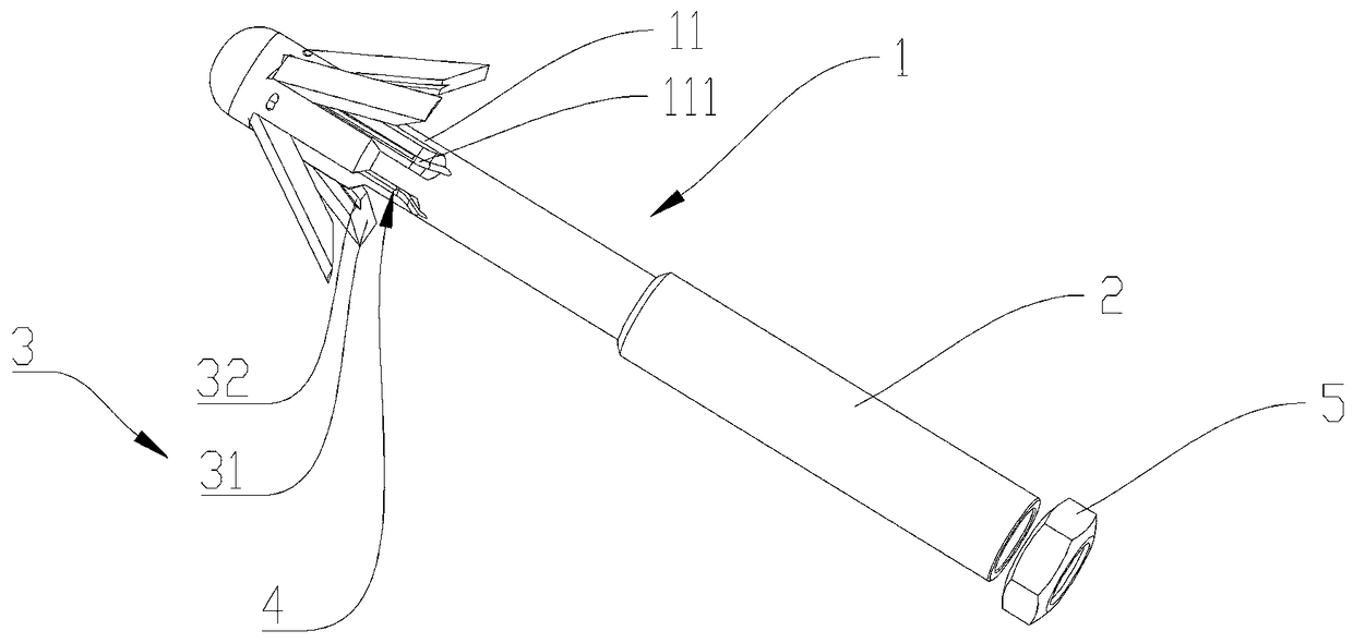
[0006] In order to solve the technical defects of the expansion anchor bolts in the prior art, which are hard to install and difficult to install, the present invention proposes a new type of expansion anchor bolt, which is used to fasten the installation base surface including the anchor rod and the ground that can reciprocate along the extension direction of the anchor rod. The sleeve is sleeved on the outer surface of the anchor rod, and the anchor rod is provided with an accommodation cavity, and the expansion body is hinged in the accommodation cavity, and the non-hinge end of the expansion element is used to abut against the expansion element. A warping member that can at least partially protrude out of the accommodating groove; the non-hinge end of the expansion member is provided with a guide surface, and the guide surface is used for abutting against one end of the sleeve until the expansion The body expands by turning its non-articulated end into contact with the mounting base

Method used


Image

  • Novel expansion anchor bolt
  • Novel expansion anchor bolt
  • Novel expansion anchor bolt

Examples


Embodiment Construction

[0020] The present invention will be described in detail below in combination with specific embodiments.

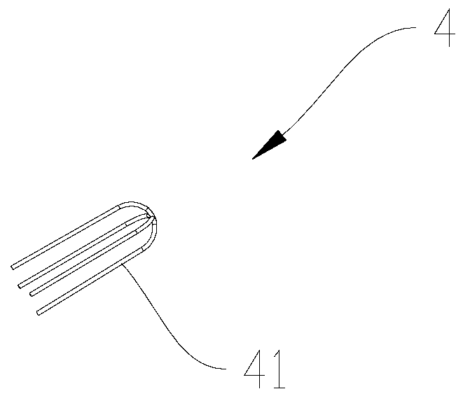
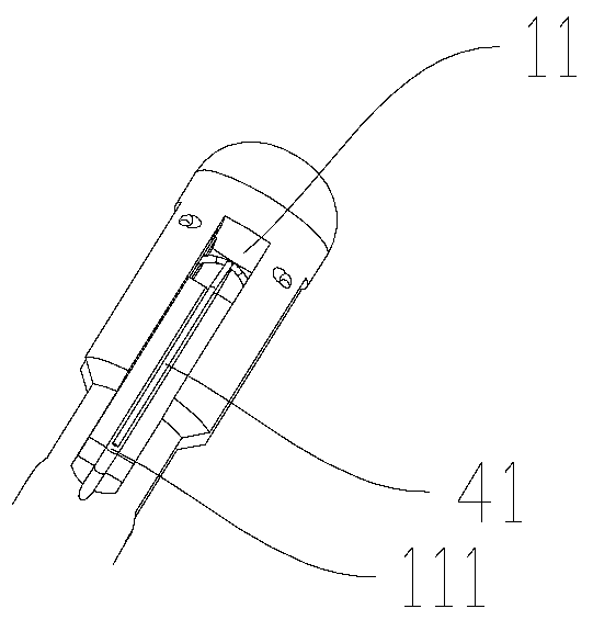
[0021] see figure 1 , figure 2 , image 3 , a new type of expansion anchor bolt of the present invention, used to fasten the installation base surface, includes an anchor rod 1 and a sleeve 2 that can reciprocate along the extension direction of the anchor rod 1 and is sleeved on the outer surface of the anchor rod 1 , the anchor rod 1 is provided with an accommodating cavity 11, the expansion body 3 is hinged in the accommodating cavity 11 and is used to make the non-hinged end of the expansion component protrude at least partially from the expansion component by abutting against the expansion component. The tilting part 4 outside the accommodating groove; the non-hinged end of the expansion part is provided with a guide surface 31, and the guide surface 31 is used for abutting against one end of the sleeve 2 until the expansion body 3 with its The non-hinged end is ...


PUM


Abstract

The invention provides a novel expansion anchor bolt, and belongs to the technical field of anchor bolt fixing. The novel expansion anchor bolt is used for fastening an installing base surface and comprises an anchor rod and a sleeve which is arranged on the outer surface of the anchor rod in a sleeving mode in the mode of doing reciprocating motion in the extending direction of the anchor rod, acontaining cavity is formed in the anchor rod, and expansion bodies and a cocking part used for being connected with the expansion bodies in a butting-joint mode to enable the non-hinged ends of the expansion bodies to be capable of at least partially protruding out of a containing groove; and the non-hinged end of each expansion body is provided with a guiding surface, and the guiding surfaces are used for being connected with one end of the sleeve in an abutting mode till the expansion bodies are expanded in the mode that the non-hinged ends rotate to make contact with the installing base surface. According to the novel expansion anchor bolt, the sleeve abuts against the guiding surfaces to enable the expansion bodies to be expanded, and the expanding and fixing effects are achieved. Thestructure is simple, anchoring can be achieved only by rotating or knocking the sleeve, labor is saved, and the expansion degree of the expansion bodies is controlled by controlling the abutting length of the sleeve.

Description

technical field [0001] The invention relates to the technical field of anchor bolt fixing, in particular to a novel expansion anchor bolt. Background technique [0002] Expansion anchor bolt, referred to as expansion bolt. It uses the relative movement between the vertebral body and the expansion sheet (or expansion sleeve) to promote the expansion of the expansion sheet, generate expansion extrusion force with the hole wall concrete, and generate pull-out force through shear friction, so as to realize the anchorage of the connected parts A component. [0003] When in use, you must first use an impact electric drill (hammer) to drill holes of corresponding size on the fixed body, then put the bolts and expansion tubes into the holes, and tighten the nuts to make the connection between the bolts, expansion tubes, mounting parts and the fixed body Tighten and become one. It will expand after tightening. There is a big head at the end of the bolt, and a round pipe slightly l...

Claims


Application Information

Patent Timeline
Patent Type & Authority Applications(China)
IPC IPC(8): F16B13/06
CPCF16B13/063
Inventor 李诗全陈小珍
Owner 百益百利(福州)幕墙工程有限公司
Learn More