Anti-lock chemical centrifugal pump

A centrifugal pump and anti-lock technology, which is applied to pumps, pump devices, pump components, etc., can solve problems such as loose connections, loose bolts, and inability to rotate the impeller, so as to avoid locking, increase sealing, and protect bearings Effect

Inactive Publication Date: 2018-11-20
南京中溧知识产权代理有限公司
View PDF0 Cites 1 Cited by
  • Summary
  • Abstract
  • Description
  • Claims
  • Application Information

AI Technical Summary

Problems solved by technology

[0002] The working principle of the chemical centrifugal pump is that when the pump is filled with water, the impeller rotates to generate centrifugal force. The pressure in the water pipe, the water flows into the impeller from the suction pool under the action of this pressure difference; the existing chemical centrifugal pumps have certain disadvantages in use. First of all, the chemical centrifugal pumps are usually connected by threads. It takes a long time, and the thread will wear out over time, and the connection will not be firm. Secondly, the chemical centrifugal pump will produce a large vibration when it is working, and the bolts through the connection are easy to loosen, causing the chemical centrifugal pump to malfunction. Finally, When the chemical centrifugal pump is pumping water, more impurities in the water will fall into the bearing of the impeller, which will cause the impeller to fail to rotate and lock up, which will have a certain impact on people's use. For this reason, we propose An anti-lock chemical centrifugal pump

Method used


Image

  • Anti-lock chemical centrifugal pump
  • Anti-lock chemical centrifugal pump
  • Anti-lock chemical centrifugal pump

Examples


Embodiment Construction

[0017] In order to make the technical means, creative features, achievement goals and effects realized by the present invention easy to understand, the present invention will be further described below with reference to the specific embodiments.

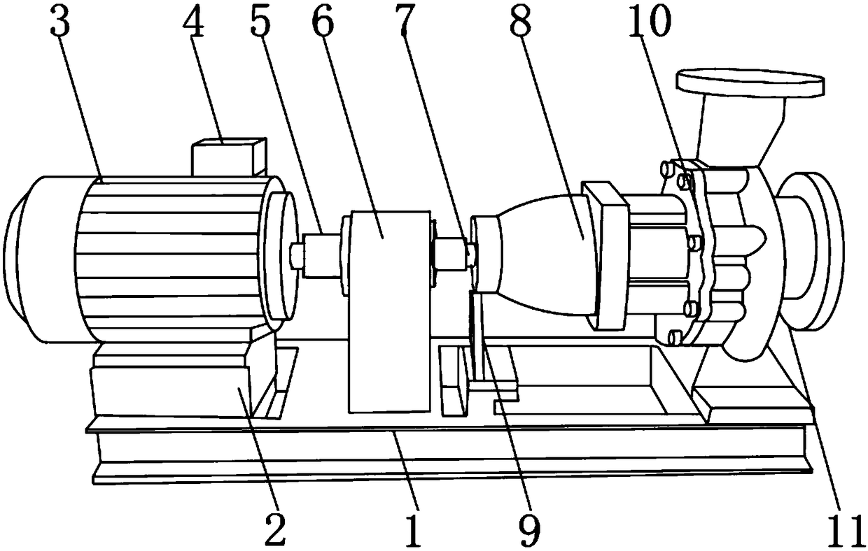
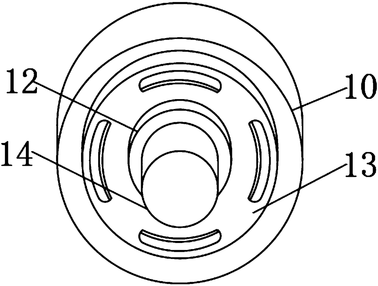
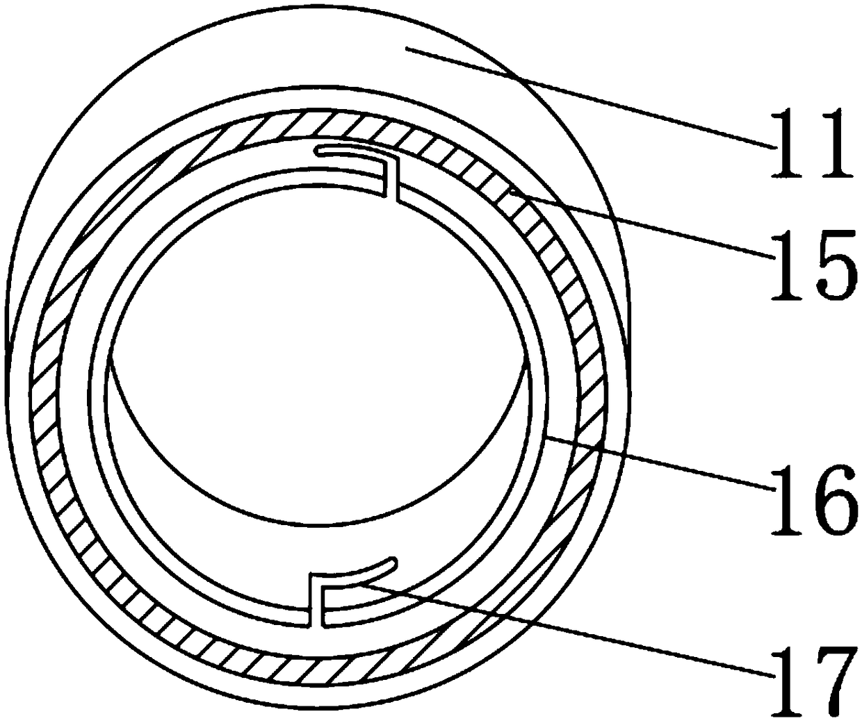
[0018] like Figure 1-4 As shown, an anti-lock chemical centrifugal pump includes a base 1, a base 2 is fixedly installed on the outer surface of the upper end of the base 1 near one side, and a motor 3 is fixedly installed on the outer surface of the upper end of the base 2, and the motor 3 An outlet box 4 is fixedly installed at the upper end near one side, and a pump shaft 5 is arranged on one side of the motor 3, an intermediate bracket 6 is arranged on the outer surface of the pump shaft 5, and a moving ring 7 is arranged at one end of the pump shaft 5, and the pump shaft One end of the pump cover 8 is provided with a pump cover 8, and the bottom end of the pump cover 8 is fixedly installed with a support plate 9 near one side, ...


PUM


Abstract

The invention discloses an anti-lock chemical centrifugal pump. The anti-lock chemical centrifugal pump comprises a bottom seat, a base is fixedly installed at the position, close to one side, of theouter surface of the upper end of the bottom seat, and a motor is fixedly installed on the outer surface of the upper end of the base. An outlet box is fixedly installed at the position, close to oneside, of the upper end of the motor, a pump shaft is arranged on one side of the motor, a middle support is arranged on the outer surface of the pump shaft, and a moving ring is arranged at one end ofthe pump shaft. A pump cover is arranged at one end of the pump shaft, a supporting plate is fixedly installed at the position, close to one side, of the bottom end of the pump cover, a pump body isfixedly installed on one side of the pump cover, and an installation ring is fixedly installed at the position, close to the middle, of one side of the pump body. The anti-lock chemical centrifugal pump is provided with a slag prevention cover, clamping grooves and a buffer plate, can prevent residues from falling into a bearing, is convenient for people to connect water pipes, can reduce the vibration caused by the chemical centrifugal pump, and brings better application prospects.

Description

technical field [0001] The invention relates to the field of chemical centrifugal pumps, in particular to an anti-lock chemical centrifugal pump. Background technique [0002] The working principle of the chemical centrifugal pump is that when the pump is filled with water, the impeller rotates to generate centrifugal force, and the water in the impeller channel is thrown to the periphery and flows into the pump casing under the action of centrifugal force, so the pressure at the center of the impeller is reduced, and this pressure is lower than the inlet pressure. Due to the pressure in the water pipe, the water flows from the suction tank into the impeller under the action of this pressure difference; the existing chemical centrifugal pump has certain drawbacks in use. First, the chemical centrifugal pump is usually connected by a threaded connection. It takes a long time, and the thread will be worn out and the connection will not be firm. Secondly, the chemical centrifug...

Claims


Application Information

Patent Timeline
IPC IPC(8): F04D13/06F04D29/70F04D29/42F04D29/08F04D29/66
CPCF04D13/06F04D29/086F04D29/426F04D29/669F04D29/708
Inventor 陆福萍
Owner 南京中溧知识产权代理有限公司
Why Eureka
Try Eureka