Shaker

a shaker and shaker technology, applied in the field of shakers, can solve the problems of contaminating other components, affecting the smooth operation of the shaker, and requiring a considerable cleaning effort, and achieve the effect of smooth operation over a longer period of time, optimum shaker operation, and smooth shaker operation

Active Publication Date: 2019-05-02
INFORS
View PDF0 Cites 0 Cited by
  • Summary
  • Abstract
  • Description
  • Claims
  • Application Information

AI Technical Summary

Benefits of technology

This patent is for a shaker that prevents contamination of samples and allows for easy cleaning. The cover of the shaker prevents liquids and solids from getting inside. The tray shaft is secured against rotation so that only the tray and the tray shaft need to be cleaned, instead of the whole shaker. The connecting element compensates for changes in distance between the tray shaft and the second tray shaft, ensuring optimal operation of the shaker. The shaker also includes one or more counterweights to balance unbalanced mass distribution and enable high shaking frequencies. Overall, this shaker is designed to be more efficient and effective in mixing samples.

Problems solved by technology

On the other hand, liquid can be spilled or sprayed on the tray during the shaking process, which can also contaminate other components such as a shaker drive.
With conventional shakers, such contamination affects numerous components, so that the necessary cleaning is a considerable effort.
The problem is therefore to design a shaker with a high shaking frequency which is designed in such a way that the cleaning effort in case of contamination is as low as possible.

Method used


Image

  • Shaker
  • Shaker

Examples


Embodiment Construction

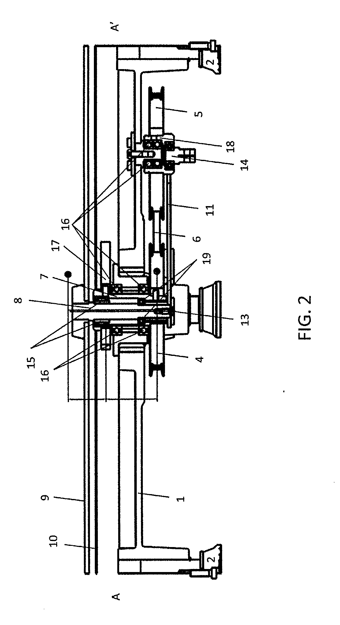
[0019]A preferred embodiment of the invention is shown in FIG. 1 and FIG. 2. FIG. 1 shows a view from below of a shaker according to an embodiment of the invention with frame 1, drive 3-6 and eccentrically mounted connecting element 11. The shaker comprises a frame 1 made of metal or plastic, for example, which stands on four feet 2.

[0020]Frame 1 is fitted with a motor, e.g. an electric motor, which drives a pulley 3. Two further pulleys 4 and 5 are driven via a toothed belt 6, which prevents slippage. These pulleys are mounted on shafts which are described in more detail below.

[0021]FIG. 2 shows a vertical section through the shaker along the diagonal A-A′ passing through the shafts of the two pulleys 4 and 5. The first belt pulley 4 driven by the toothed belt 6 is mounted on a hollow shaft 7, which is rotatably mounted on the frame 1 via ball bearings 16. The second belt pulley 5, driven by the toothed belt 6, is mounted on a second hollow shaft 18, which is also preferably mounte...


PUM


Abstract

Shaker comprising a frame, a tray for receiving one or more samples and a drive for the tray, in which a tray shaft is mounted eccentrically in a drivable hollow shaft. The tray shaft is fixedly connected to the tray and secured against rotation relative to the frame.

Description

CROSS REFERENCE TO RELATED APPLICATIONS[0001]This application claims foreign priority benefits under U.S.C § 119 to European patent application EP 17 199 729.9, filed on Nov. 2, 2017, the content of which is hereby incorporated by reference in its entirety.FIELD OF THE INVENTION[0002]The invention concerns a shaker, in particular a laboratory shaker, in particular for shaking and / or mixing samples containing liquids.BACKGROUND ART[0003]Shakers are used to shake and / or mix liquids, e.g. cell cultures, biofuels or blood samples, in vessels. The shaken unit often comprises a tray on which the vessels, e.g. Erlenmeyer flasks, test tubes or other ampoules containing the samples, are placed. On the one hand, a high shaking frequency is desirable. On the other hand, liquid can be spilled or sprayed on the tray during the shaking process, which can also contaminate other components such as a shaker drive. With conventional shakers, such contamination affects numerous components, so that the...

Claims


Application Information

Patent Timeline
Patent Type & Authority Applications(United States)
IPC IPC(8): B01F11/00
CPCB01F11/0014B01F11/0008B01F11/0031B01L9/00B01F2215/0481B01F31/22B01F31/201B01F31/265
Inventor HAWRYLENKO, ALEXANDER
Owner INFORS
Why Eureka
Try Eureka