
Horizontal overturning door

A flap door and door panel technology, which is applied in water conservancy projects, sea area projects, coastline protection, etc., can solve the problems that the curved arm steel dam gate cannot be installed and used in parallel with multiple leaves, the structure is complicated and complicated, and the four-bar structure is complicated. , to achieve simple structure, reduce energy consumption, and avoid the impact of water flow

Pending Publication Date: 2018-11-20
衢州市江汇翻板闸门有限公司
View PDF1 Cites 0 Cited by
  • Summary
  • Abstract
  • Description
  • Claims
  • Application Information

AI Technical Summary

Problems solved by technology

The disadvantages of the curved arm steel dam gate are: 1. The four-bar structure is relatively complicated, and water baffles need to be installed on the steel dam door leaf; Connect the forward-extending crank arm, so there will be gaps on both sides of the steel dam gate, so this kind of crank-arm steel dam gate cannot be installed and used in a row. When it is used alone, once the width of the river is too wide, the water storage The height is large, and it is quite difficult to realize the up and down swing of the huge steel dam gate leaf through one opening and closing cylinder. If multiple opening and closing cylinders are used on a huge steel dam gate, it will inevitably be due to the extension of time. When the oil cylinders are subjected to different degrees of aging due to river water erosion, it is difficult for each opening and closing cylinder to operate on the steel dam gate leaves at the same time. Therefore, the application scenarios of such crank arm steel dam gates are limited, only in places with small flow and narrow river channels; 3. In order to achieve the purpose of covering the opening and closing oil cylinder, claims 5 and 6 stipulate that the curved arm steel dam gate needs to be provided with a cover plate, and it needs to be placed on the left and right sides of the opening and closing oil cylinder. The limit rod is used to ensure that the cover plate is covered above the opening and closing oil cylinder when the steel dam door leaf swings, and the structure is complicated
And from here, it can also be confirmed that this kind of flap gate is only suitable for places with narrow river channels, and external extension rods need to be installed on the walls on both sides of the river channel, indicating that the river channel is very narrow

Method used


Image

  • Horizontal overturning door
  • Horizontal overturning door
  • Horizontal overturning door

Examples


Embodiment 1

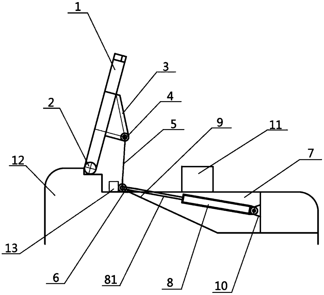
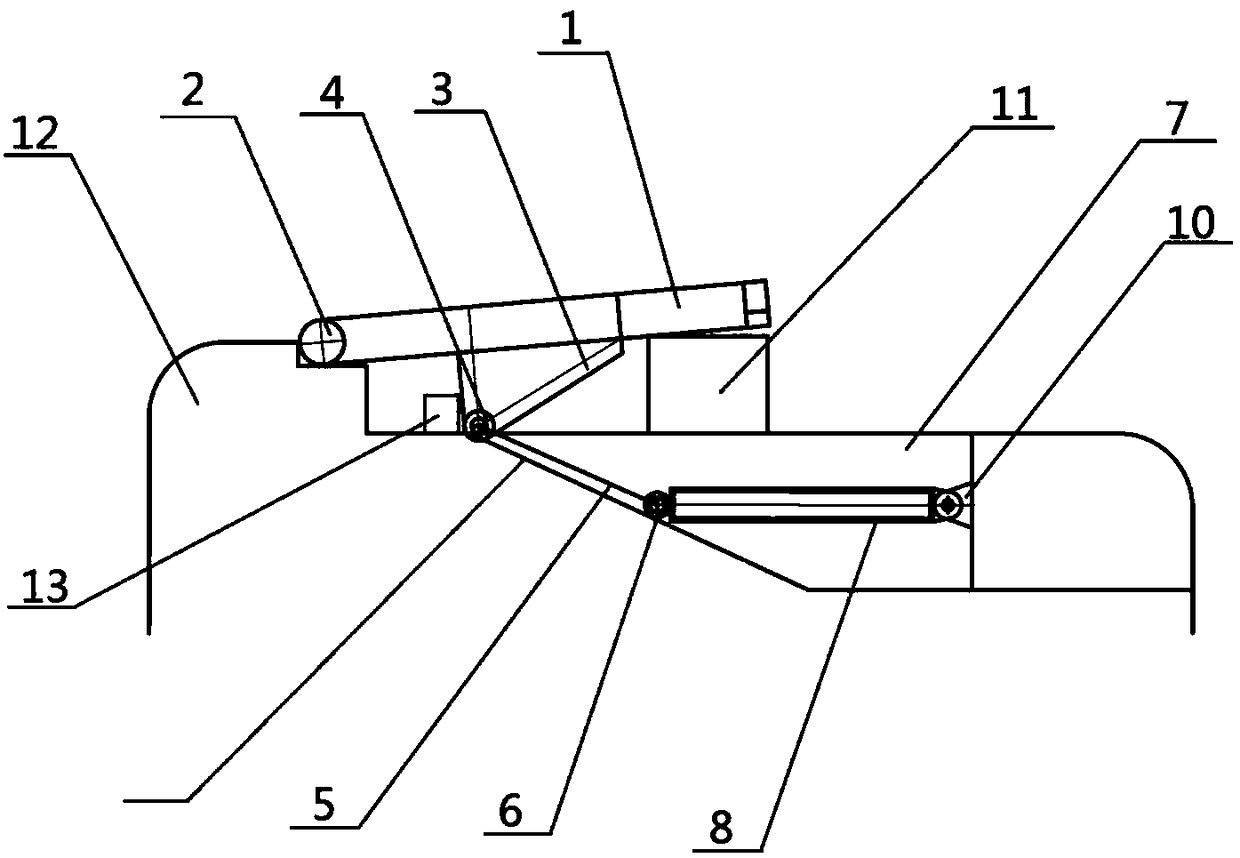
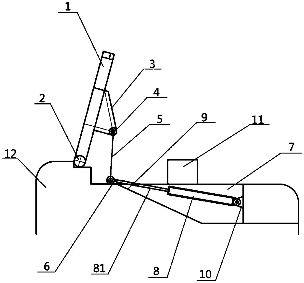
[0036] Such as figure 1As shown, when it is necessary to lift the dam and stop water, the opening and closing cylinder 8 is started, and the control piston rod 81 is stretched out from the opening and closing cylinder 8, and the movable joint 6 of the support rod is pushed to move upward along the sliding track 9, and the support rod 5 passes through the support The hinge 4 jacks up the door panel 1 originally horizontally mounted on the pier 11, and the door panel 1 starts to swing up around the bottom shaft 2, and the piston rod 81 pushes the movable joint 6 of the support rod to the uppermost edge of the sliding track 9. At this time, the support rod 5 and the The horizontal planes are 80-88°. In order to prevent the piston rod 81 from pushing the support rod movable joint 6 over the head, a support rod limit column 13 is formed on the slide track 9 along the other side of the support rod movable joint 6 . The support rod movable joint 6 cannot be pushed forward after bein...

Embodiment 2

[0039] Such as image 3 As shown, in this embodiment, the maximum amount of the extension length of the piston rod 81 is the length to push the support rod movable joint 6 to the position in Embodiment 1 when the operation of raising the dam and blocking water is completed. When the piston rod 81 extends When the amount is the largest, it is 80-88° between the support rod 5 and the horizontal plane. Therefore, in this embodiment, there is no need for the support rod limiting post 13 . When it is necessary to raise the dam and stop the water, the opening and closing cylinder 8 is activated, and the control piston rod 81 protrudes from the opening and closing cylinder 8 to push the movable joint 6 of the support rod to move upward along the sliding track 9, and the support rod 5 is lifted by the bracket hinge 4. Lift the door panel 1 that was originally placed on the support pier 11, and the door panel 1 starts to swing up around the bottom shaft 2, and the piston rod 81 pushes...

Embodiment 3

[0042] In this embodiment, the bracket hinge 4 is directly installed on the back surface of the door panel 1, compared with the embodiment 1, the bracket 3 is omitted, and other structures are consistent with the embodiment.


PUM


Abstract

The invention discloses a horizontal overturning door, and belongs to the field of dam structure in water conservancy facilities. The horizontal overturning door comprises a door sheet. The bottom ofthe door sheet is connected with a hinge mounted at a dam body by a bottom shaft. The door sheet swings around the bottom shaft. When the door sheet swings upwards, water blocking is achieved, and when the door sheet swings downwards, water drainage is achieved. A supporting bracket is arranged on the downstream face of the door sheet. A supporting frame hinge is arranged at the supporting frame.The dam body is internally provided with a dam body preformed hole. A dam body starting and stopping device is arranged in the dam body preformed hole. The dam body starting and stopping device is connected with the supporting bracket hinge by a supporting rod and controls the door sheet to swing upwards and downwards. The horizontal overturning door has the beneficial effects that the supportingbracket is arranged on the downstream face of the door sheet; the supporting rod is mounted at the supporting bracket and can shorten the length of the supporting rod; and when the length of the supporting rod is shortened, bending strength of the supporting rod is improved, and therefore stroke of an oil cylinder is shortened, and the width of the cross section of the dam is shortened, so that investment of the dam is reduced.

Description

technical field [0001] The invention relates to a dam body structure of a water conservancy facility, in particular to a flap gate. Background technique [0002] Steel gate is an important mechanical equipment in water conservancy and hydropower engineering facilities. It is mainly used in the construction of agricultural irrigation, fishery, ship locks, seawater tidal protection, urban river landscape engineering and small hydropower stations. The usual steel plate gate is a new type of gate that is opened and closed just after the gate is opened and closed by driving the horizontal axis of the bottom driven by hydraulic equipment. It has the characteristics of rapid opening and closing and durability. It mainly includes the bottom horizontal shaft, the steel dam door leaf, the hoist installed in the sluice chamber, etc. The steel dam door leaf is connected with the bottom horizontal shaft to form a gate, and the two ends of the bottom horizontal shaft pass through the wal...

Claims


Application Information

Patent Timeline
IPC IPC(8): E02B7/40
CPCE02B7/40
Inventor 吴晓峰
Owner 衢州市江汇翻板闸门有限公司
Learn More