
Gas cyclone pollutant collecting culture pond system

A technology of aquaculture ponds and flow sets, applied in the field of aquaculture pond systems, can solve the problems of easy to cause turbulence, low water flow stability, low sewage absorption efficiency, etc., and achieve stable water inlet dynamics, high water flow stability, and drainage stability. high effect

Active Publication Date: 2018-11-20
FISHERY MACHINERY & INSTR RES INST CHINESE ACADEMY OF FISHERY SCI
View PDF3 Cites 8 Cited by
  • Summary
  • Abstract
  • Description
  • Claims
  • Application Information

AI Technical Summary

Problems solved by technology

[0004] 1) Due to the low sewage suction efficiency of the sewage suction device, the fish feces cannot be discharged from the pond in time and return to the water body, seriously polluting the aquaculture water body;
[0005] 2) The fish are concentrated in the oxygenation area in the front section, and the density is high, which causes serious friction between fish and easily causes skin damage, resulting in frequent occurrence of diseases, which brings greater risks to farming;
[0006] 3) The air lift plugging device directly acts on the culture pond, the water flow stability in the culture pond is low, and it is easy to cause turbulent flow, which has an adverse effect on the growth of fish;
[0007] 4) Unstable drainage, resulting in poor water quality or waste of water resources

Method used


Image

  • Gas cyclone pollutant collecting culture pond system
  • Gas cyclone pollutant collecting culture pond system
  • Gas cyclone pollutant collecting culture pond system

Examples


Embodiment Construction

[0034] The present invention will be further described below in conjunction with the accompanying drawings and specific embodiments.

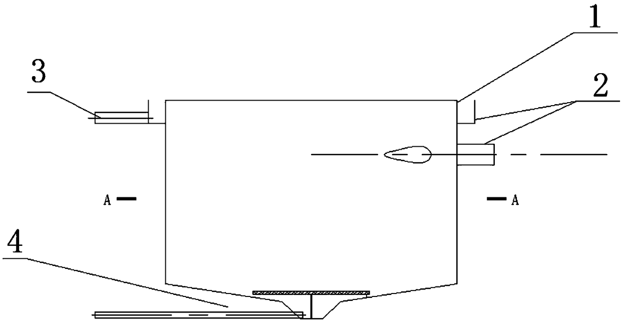
[0035] In traditional aquaculture ponds, construct a high-efficiency sewage collection circular aquaculture pond system according to 4-6% of the pond water surface area. The water depth is not less than 2.0m, which is used for high-density intensive cultivation of fish, and the rest of the pond area is used as a water purification area. The discharge water from the high-efficiency sewage collection circular aquaculture pond system is purified by the water purification zone and returned to the circular pond for reuse to realize the internal circulation of the water body.

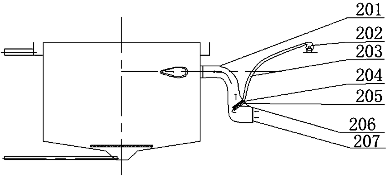
[0036] The culture pond system includes a circular culture pond body 1, an inflow aeration pushing flow system 2, an upper drainage system 3, and a bottom sewage system 4; the bottom of the circular culture pond body 1 is inclined towards the central sewage pit; The water inle...


PUM

PropertyMeasurementUnit
Diameteraaaaaaaaaa

Abstract

The invention relates to a gas cyclone pollutant collecting culture pond system. An air inlet aerating plug flow system comprises a guide barrel. A baffle plate is fixedly arranged on the inner wall of the guide barrel through a supporting rack, a group of aerating heads are arranged behind the water inlet direction of the baffle plate and the aerating heads are connected to a Roots blower locatedout of the guide barrel through a gas conveying pipe; the water outlet of the guide barrel is formed tangentially in the side wall of the round culture pond; an upper drainage system comprises a triangular downflow weir. The triangular downflow weir is located on the upper parts around the circular culture pond, and a ring of braiding channel is arranged in a position below the triangular downflow weir of the round culture pond; a pollutant collecting pit of a bottom pollution discharge system is located at the lowest position of the center of the bottom of the round culture pond and a net fish screen is horizontally placed on the pollutant collecting pit. The system improves the collecting efficiency of feces and residual feeds in a high density fish pond, so that the pollution load of the fish pond is alleviated; the water inlet power is stable, the water flow stability in the culture pond is relatively high, turbulence is avoided, and growth of fishes in water is facilitated.

Description

technical field [0001] The invention relates to a culture pond system, in particular to a culture pond system for gas swirling sewage collection. Background technique [0002] The pond runway type micro-flow ecological breeding mode has developed rapidly in Jiangsu, Zhejiang, Anhui, Guangdong, Shandong and other places in my country in recent years. At the water end, an air lift push flow device is used to push the water body into the flow tank, flow through the breeding area, and flow out from the terminal sewage collection area. During this process, the remaining feed and feces of the aquatic animals are taken away by the water flow and collected to the terminal sewage collection The area is removed by the sewage suction device. This mode has the characteristics of land saving, energy saving, high efficiency and emission reduction. [0003] But there are following problems: [0004] 1) Due to the low sewage suction efficiency of the sewage suction device, the fish feces ca...

Claims


Application Information

Patent Timeline
IPC IPC(8): A01K63/00A01K63/04
CPCA01K63/00A01K63/04A01K63/042
Inventor 程果锋刘兴国朱浩王建
Owner FISHERY MACHINERY & INSTR RES INST CHINESE ACADEMY OF FISHERY SCI
Learn More