
Chip test system

A chip testing and chip technology, which is applied in the direction of measuring devices, measuring electrical variables, measuring device casings, etc., can solve problems such as damage and unable to rule out chip test bases

Inactive Publication Date: 2018-11-16
SUZHOU TF AMD SEMICON CO LTD
View PDF8 Cites 2 Cited by
  • Summary
  • Abstract
  • Description
  • Claims
  • Application Information

AI Technical Summary

Problems solved by technology

[0005] The technical problem solved by the present invention is that in the chip testing process, there is no specific standard to judge when the chip test base should be overhauled, resulting in many cases when the test fails and cannot be ruled out as the cause of the damage of the chip test base

Method used


Image

  • Chip test system

Examples


Embodiment Construction

[0023] In the prior art, after continuous test failures occur during the chip testing process, the test is usually stopped, and the specific reasons for the test failures are determined based on the experience of engineers, resulting in a longer cycle of chip testing.

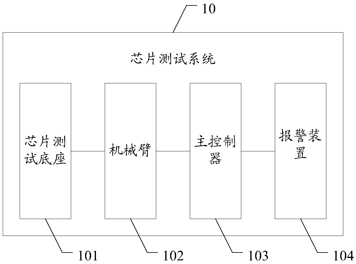
[0024] In the embodiment of the present invention, an identification mark is set on the surface of the chip test base, and each time the robot arm places a chip on the chip test base, the identification sensor on the mechanical arm recognizes the identification mark corresponding to the chip test base , the main controller records the usage times of the chip test base according to the identification times of the identification identification sensor. By reasonably setting the maximum number of times of use, when the number of times of use of the chip test base is reached, the main controller will alarm and remind to replace or overhaul the chip test base to ensure the process of chip testing. At the same time, th...


PUM


Abstract

A chip test system comprises a chip test pedestal, a mechanical arm, an alarm device and a main controller. The surface of the chip test pedestal is provided with a corresponding identifier; the mechanical arm is configured to perform operation of the chip when a control command output by the main controller is received to put the chip at the chip test pedestal or separate the chip from the chip test pedestal; the mechanical arm is provided with an identifier identification sensor configured to identify the identifier of the chip test pedestal when the mechanical arm performs operation of thechip and send the identification information obtained through identification to the main controller; the main controller is suitable for receiving of the identification information sent by the mechanical arm and record the number of current usage times of the chip test pedestal; and the main controller outputs alarm signals to the alarm device when it is detected that the number of the current usage times of the chip test pedestal reaches the preset maximum number of times. The technical scheme provides a standard for when the chip test pedestal should be maintained or replaced.

Description

technical field [0001] The invention relates to the field of chip testing, in particular to a chip testing system. Background technique [0002] In current chip testing, both automatic test equipment (Automatic Test Equipment, ATE) and system level testing (System Level Test, SLT) processes involve the use of a chip test socket (socket). [0003] When a test failure result occurs during the use of the chip test base, it is impossible to directly determine whether the cause of the test failure is damage to the chip test base or a problem with the chip itself, which ultimately affects the testing process. [0004] In the prior art, after consecutive test failures, the test is usually stopped, and the engineer's experience is relied on to determine the specific cause of the test failure, resulting in a longer cycle of chip testing. Contents of the invention [0005] The technical problem solved by the present invention is that in the chip testing process, there is no specifi...

Claims


Application Information

Patent Timeline
IPC IPC(8): G01R1/04G01R35/00
CPCG01R1/0416G01R1/0483G01R35/00
Inventor 吴欢欢
Owner SUZHOU TF AMD SEMICON CO LTD
Learn More