
Electric vehicle charging device for single-layer garage

A charging device and technology for electric vehicles, applied in the direction of electric vehicle charging technology, electric vehicles, buildings where cars are parked, etc., can solve the problems of waste of resources, high charging costs, etc., and achieve the effect of prolonging the service life and reducing the height

Active Publication Date: 2018-11-16
GUANGZHOU YUXUAN INFORMATION TECH CO LTD
View PDF6 Cites 2 Cited by
  • Summary
  • Abstract
  • Description
  • Claims
  • Application Information

AI Technical Summary

Problems solved by technology

[0003] The present invention proposes an electric vehicle charging device for single-storey garages, which can solve the problem of high charging costs for electric vehicles and avoid waste of resources on the basis of renovating existing single-storey garages without major actions

Method used


Image

  • Electric vehicle charging device for single-layer garage
  • Electric vehicle charging device for single-layer garage

Examples


Embodiment 1

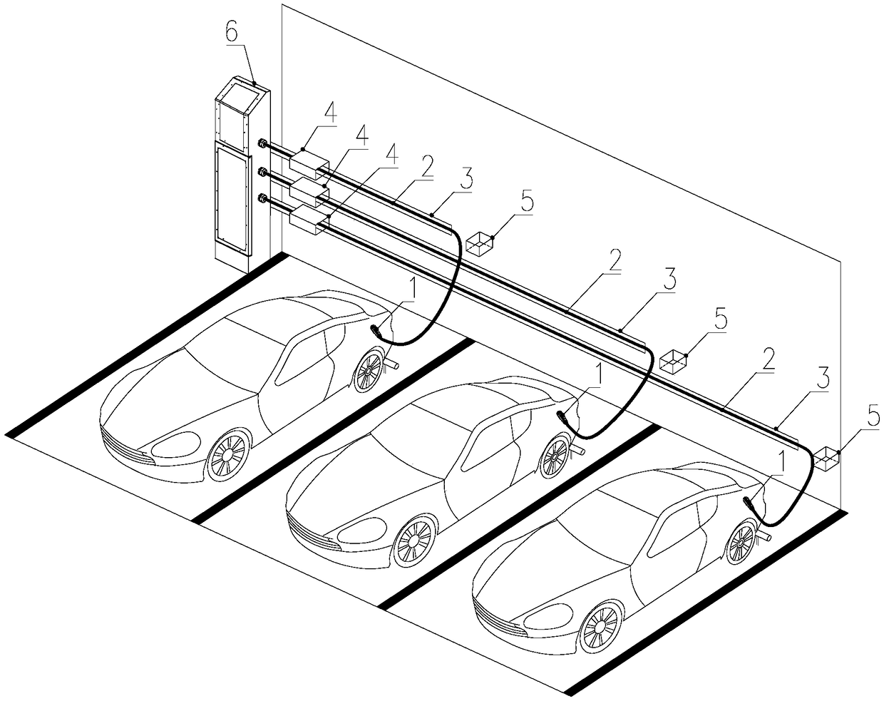
[0029] Such as figure 1 As shown, an electric vehicle charging device for a single-storey garage is fixed on the wall and installed in indoor and outdoor parking lots. It is suitable for 3 parking spaces near the wall and can charge various types of electric vehicles according to different voltage levels. Car charging, the charging device includes 3 charging guns 1, 3 gun lines 2 and 1 charging power supply 6, one end of each gun line 2 is connected to a charging gun 1, and the other end is connected to the charging power supply 6.

[0030] In this technical solution, the input end of the charging power supply 6 is directly connected to the AC power grid, and the output end is connected to the charging gun 1 through the gun wire 2. When the user needs to charge, the operation before charging is carried out by means of mobile phone scanning code or magnetic card induction. Afterwards, the charging gun 1 is inserted into the charging port of the electric vehicle, and the chargin...

Embodiment 2

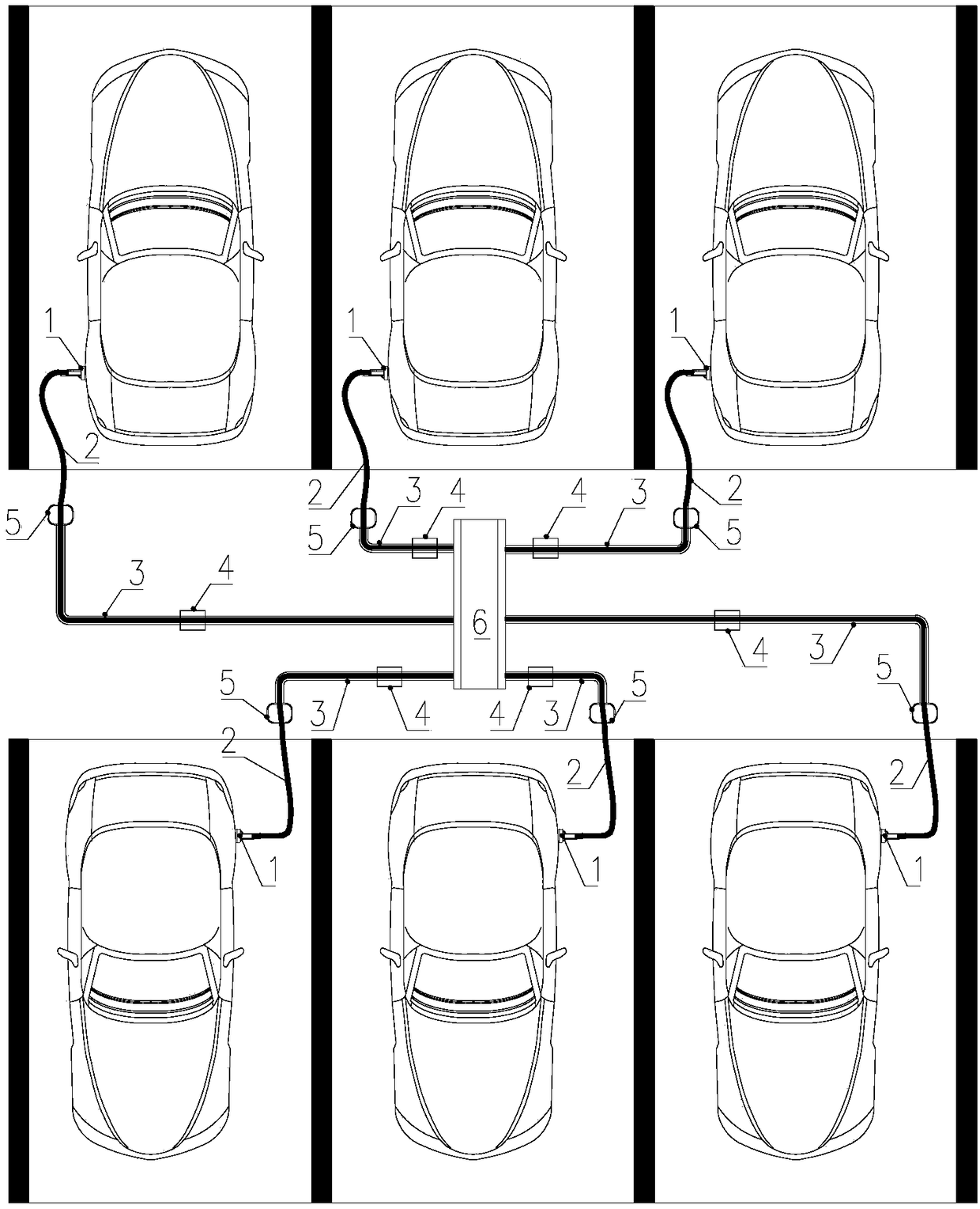
[0041] An electric vehicle charging device for a single-storey garage, fixed on the ground, installed in indoor and outdoor parking lots, suitable for parking spaces in the middle of the parking lot; for the parking spaces in the middle of the parking lot, each group of 6 parking spaces, Specifically, there are three cars in each row, a total of two rows, limited by the limit bar of the parking space, and the rear of the vehicle is facing each other after parking; there is a certain distance between the two rows of limit bars, and the space is large, and a horizontal charging power supply can be installed 6 , reduce the height of charging power source 6, avoid affecting the driver's line of sight.

[0042] Such as figure 2 As shown, the charging device in this embodiment includes 6 charging guns 1, 6 charging wires 2 and 1 charging power source 6. One end of each charging wire 2 is connected to a charging gun 1, and the other end is connected to the charging power source 6. ...


PUM


Abstract

The invention relates to the field of charging piles, in particular to an electric vehicle charging device for a single-layer garage, comprising multiple charging guns, multiple gun lines and a charging power supply, wherein one end of each gun line is connected with one charging gun, and the other end of each gun line is connected with the charging power supply; the charging device further comprises multiple sliding guide devices arranged on the wall or the ground; the gun lines are penetratingly arranged on the sliding guide devices and move along the same; the charging device further comprises gun line retracting and releasing devices arranged between the charging power supply and charging gun holders; the charging device further comprises the charging gun holders arranged on the wall or the ground, and the charging guns and the charging gun holders are provided with induction devices; the gun line retracting and releasing devices are provided with control equipment connected with the induction devices. According to the invention, the charging device can solve the problem of charging difficulty of electric vehicles and avoid waste of resources on the basis of not greatly transforming an existing single-layer garage.

Description

technical field [0001] The invention relates to the field of charging piles, in particular to an electric vehicle charging device for a single-storey garage. Background technique [0002] With the development and use of clean energy, the market for electric vehicles is gradually increasing, followed by the problem of insufficient charging piles in the existing parking lots, especially in the parking lots. If the parking spaces are re-planned and transformed, The cost required is huge, and the planning and renovation process will also increase the burden on the already tight parking spaces in the city; if a charging pile is installed in each parking space, on the one hand, the cost will be higher, and on the other hand, there will be problems due to no cars during off-peak hours. The waste of resources caused by use, therefore, there is an urgent need for an electric vehicle charging device for single-storey garages. Contents of the invention [0003] The present invention...

Claims


Application Information

Patent Timeline
Patent Type & Authority Applications(China)
IPC IPC(8): B60L11/18E04H6/42
CPCE04H6/42Y02T10/70Y02T10/7072Y02T90/12Y02T90/14
Inventor 郑永坤
Owner GUANGZHOU YUXUAN INFORMATION TECH CO LTD
Learn More