
A kind of concrete surface treatment equipment and its surface treatment process

A concrete surface and treatment equipment technology, applied in the field of construction, can solve problems such as increased labor, fluctuations in product quality, failure to meet the requirements of concrete surface treatment, etc., and achieve the effect of improving rubbing

Active Publication Date: 2020-10-02
GUANGDONG LIANCHENG RESIDENTIAL EQUIP INFORMATION TECH CO LTD
View PDF4 Cites 0 Cited by
  • Summary
  • Abstract
  • Description
  • Claims
  • Application Information

AI Technical Summary

Problems solved by technology

(5) At present, most of the prefabricated components have a lot of embedded sleeve bolts and wire boxes in the design, and the use of vertical vibration or shaking vibration sometimes cannot meet the requirements of concrete surface treatment (concrete surface treatment requires surface There is a certain thickness of slurry layer, and at the same time, the whole concrete cannot produce delamination effect)
The above three methods either reduce the surface requirements of the components and sacrifice the appearance quality, or meet the product requirements by increasing labor, which increases the labor cost of the product, and the product quality also fluctuates due to changes in personnel

Method used


Image

  • A kind of concrete surface treatment equipment and its surface treatment process
  • A kind of concrete surface treatment equipment and its surface treatment process
  • A kind of concrete surface treatment equipment and its surface treatment process

Examples


Embodiment

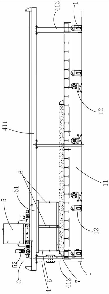
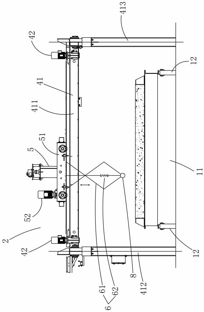
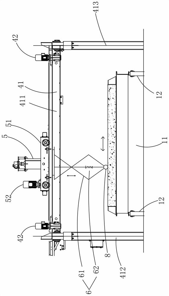
[0037] Example, combined with Figure 1 to Figure 7 As shown, a concrete surface treatment equipment includes a track 1, a moving device 2 and a rubbing device 3.

[0038]The mobile device 2 includes a longitudinal movement mechanism 4 and a lateral movement mechanism 5, the longitudinal movement mechanism 4 includes a bracket 41 and a bracket driving assembly 42, the bracket 41 includes a first leg 412, a second leg 413 and a beam 411, the One end of the beam 411 is connected to the first leg 412, and the other end of the beam 411 is connected to the second leg 413. The first leg 412 and the second leg 413 are respectively seated on the track 1. The bracket drive assembly 42 is connected to the bracket 41, and the bracket The driving assembly 42 drives the bracket 41 to move along the guide rail 1 in the Y-axis direction.

[0039] The lateral movement mechanism 5 includes a sliding bracket 51 and a sliding bracket driving assembly 52, the sliding bracket 51 is seated on the ...


PUM


Abstract

The invention relates to concrete surface treating equipment which comprises a track, a moving device and a flattening device. The moving device comprises a longitudinal moving mechanism and a transverse moving mechanism. The longitudinal moving mechanism comprises a support and a support driving assembly. The support is located on the track, the support driving assembly is connected with the support and drives the support to slide along the track, the support comprises a cross beam, the transverse moving mechanism comprises a sliding support and a sliding support driving assembly, the slidingsupport is located on the cross beam, and the sliding support driving assembly is connected with the sliding support and drives the sliding support to slide along the cross beam. The flattening device comprises a telescopic connection rod device and a flattening vibrator. The upper end of the telescopic connection rod device is connected with the sliding support, and the lower end of the telescopic connection rod device is connected with the flattening vibrator. The flattening vibrator carries out reciprocating vibration and flattening on the concrete surface in the X-axis and Y-axis directions, and automatic working procedures of vibration and flattening are achieved.

Description

technical field [0001] The invention relates to the construction field, in particular to a concrete surface treatment equipment and a surface treatment process thereof. Background technique [0002] At present, in the production of PC prefabricated components in the industry, 90% of the factories adopt the production process of flat die assembly line. This process has requirements for takt time and quality for the production of prefabricated walls (inner walls and outer walls); among them, there are three key processes " The main functions of vibrating, rubbing and smoothing are to improve the compactness of the component, the flatness of the surface and the appearance quality. According to the requirements of the national standard, the flatness of the surface of the component must be ≤5mm. [0003] At present, when the PC production line produces prefabricated wall panels, there are mainly the following methods for vibrating and rubbing the concrete: (1) The vertical vibrat...

Claims


Application Information

Patent Timeline
Patent Type & Authority Patents(China)
IPC IPC(8): B28B11/00B28B11/08
CPCB28B11/00B28B11/08
Inventor 牛巍巍其他发明人请求不公开姓名
Owner GUANGDONG LIANCHENG RESIDENTIAL EQUIP INFORMATION TECH CO LTD
Learn More