Floating cutter based on lead screw transmission

A floating cutting and cutting device technology, applied in metal processing and other directions, can solve the problems of difficult coincidence, waste of human resources, waste of time, etc., and achieve the effect of extending cutting length and improving quality

Inactive Publication Date: 2018-11-16
董莉
View PDF0 Cites 0 Cited by
  • Summary
  • Abstract
  • Description
  • Claims
  • Application Information

AI Technical Summary

Problems solved by technology

[0002] At present, when the cutting machine is cutting materials, if it is necessary to cut a long distance, it is usually done by moving the cut piece, and when moving the cut piece, for the sake of safety, it is often necessary to close the cutting machine, which not only wastes time, and waste of human resources
[0003] When moving the piece to be cut, it is also difficult for the cutting position of the piece to be cut to coincide with the last cutting position, which also greatly affects the cutting quality

Method used


Image

  • Floating cutter based on lead screw transmission

Examples


Embodiment Construction

[0012] The present invention will be further described below in conjunction with the embodiments and with reference to the accompanying drawings. It should be understood that the following specific embodiments are only used to illustrate the present invention and are not intended to limit the scope of the present invention. It should be noted that the words "front", "rear", "left", "right", "upper" and "lower" used in the following description refer to the direction in the figure, and the words "inner" and "outer ” refer to directions towards or away from the geometric center of a particular part, respectively.

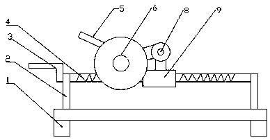
[0013] Such as figure 1 The described floating cutting device based on screw drive includes a frame 1, and the frame 1 is provided with a support frame 2, and the support frame 2 has two pieces, which are respectively located on the left and right sides of the frame 1. , and welded on the frame 1, the upper end of the support frame 2 is covered with a lead screw 4, t...


PUM


Abstract

The invention discloses a floating cutter based on lead screw transmission. The floating cutter comprises a rack which is provided with support frames, and the two support frames are provided, and located on the right and left sides of the rack separately; the upper end of each support frame is provided with a lead screw in a sleeving manner, and each screw rod is provided with a sleeve fixedly connected to a movable bracket; the tail end of each movable bracket is connected to a cutting device which is provided with a handle; and the left end of each lead screw is fixedly connected to a rocker. The cutting device can be moved through swing of the rocker horizontally, and the cutting length of the cutter is prolonged indirectly; and the cutting quality is improved, and the time and labor forces for moving materials during cutting are further saved.

Description

technical field [0001] The invention relates to a cutting device, in particular to a floating cutting device based on screw drive. Background technique [0002] At present, when the cutting machine is cutting materials, if it is necessary to cut a long distance, it is usually done by moving the cut piece, and when moving the cut piece, for the sake of safety, it is often necessary to close the cutting machine, which not only wastes time, and waste of human resources [0003] And when moving the piece to be cut, it is also difficult for the cutting position of the piece to be cut to coincide with the last cutting position, which also greatly affects the cutting quality. Contents of the invention [0004] The object of the present invention is to overcome the above problems and provide a floating cutting device based on screw drive. [0005] In order to achieve the above object, the method adopted in the present invention is: a floating cutting device based on screw drive,...

Claims


Application Information

Patent Timeline
IPC IPC(8): B26D7/00
CPCB26D7/00
Inventor 董莉
Owner 董莉
Why Eureka
Try Eureka