Magnet dismounting and mounting tool

A tooling and magnet technology, applied in the field of magnet disassembly tooling, can solve the problems of heavy workload, low work efficiency, high labor intensity, etc.

Pending Publication Date: 2018-11-16
东晶电子金华有限公司
View PDF9 Cites 1 Cited by
  • Summary
  • Abstract
  • Description
  • Claims
  • Application Information

AI Technical Summary

Problems solved by technology

Due to the inconsistency of the direction of the magnet, it is necessary to confirm and adjust the position direction of the magnet hole on the bottom plate of the fixture manually during the process of installing the magnet, which is a huge workload, high labor intensity and low work efficiency.

Method used


Image

  • Magnet dismounting and mounting tool
  • Magnet dismounting and mounting tool

Examples


Embodiment Construction

[0043] In order to understand the above-mentioned purpose, features and advantages of the present invention more clearly, the present invention will be further described in detail below in conjunction with the accompanying drawings and specific embodiments. It should be noted that, in the case of no conflict, the embodiments of the present application and the features in the embodiments can be combined with each other.

[0044] In the following description, many specific details are set forth in order to fully understand the present invention. However, the present invention can also be implemented in other ways than described here. Therefore, the protection scope of the present invention is not limited by the specific implementation disclosed below. Example limitations.

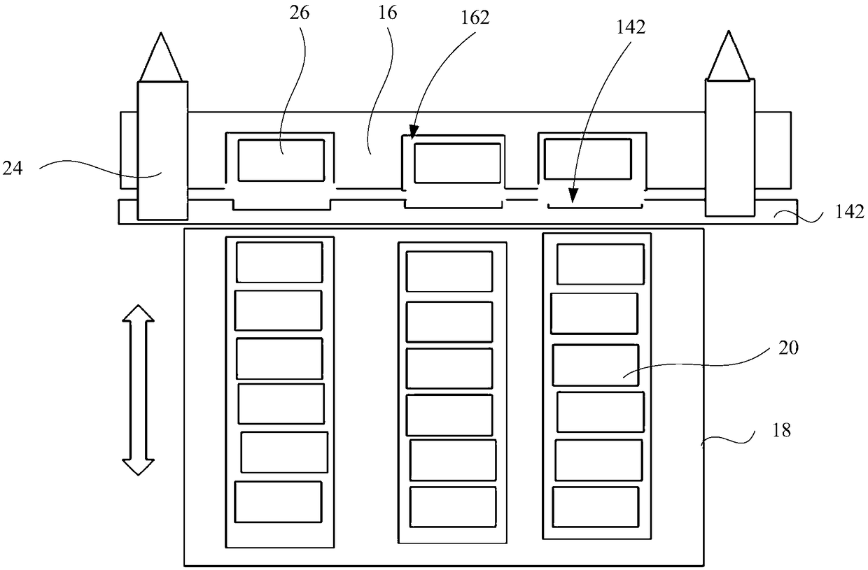
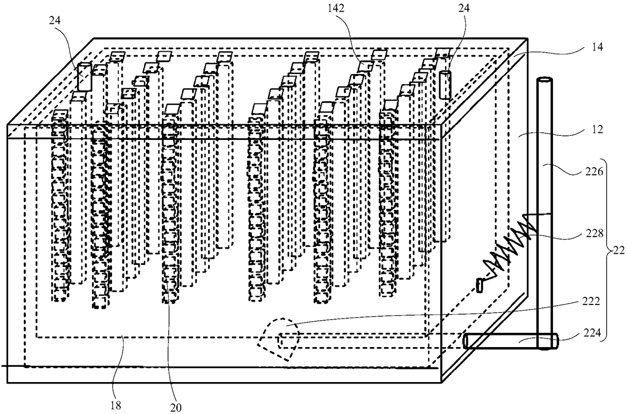
[0045] Refer below figure 1 with figure 2 Let's describe the tool for disassembling and assembling magnets according to one embodiment of the present invention.

[0046] figure 1 with figure 2 As shown...


PUM


Abstract

The invention provides a magnet dismounting and mounting tool. The magnet dismounting and mounting tool comprises a tool body, a magnet base platform, a film coating clamp, fixing blocks, a pluralityof magnetic pillars and a driving assembly; the magnet base platform is located on the top of the tool body, and a plurality of positioning grooves are formed in the top face of the magnet base platform; a plurality of magnets are attracted to one face of the film coating clamp, the film coating clamp is detachably placed on the magnet base platform, and therefore the multiple positioning groovesare opposite to the multiple magnets; the fixing blocks are located at the bottom of the magnet base platform and are internally provided with hollow containing cavities; the multiple magnetic pillars are arranged in the containing cavities; and the driving assembly is connected with the fixing blocks and is used for driving the fixing blocks to get close to the magnet base platform or be far away from the magnet base platform. The magnet dismounting and mounting tool is provided with the driving assembly to drive the upper and lower fixing blocks to move, manual dismounting and mounting oneby one during magnet dismounting and mounting is avoided, the workload is reduced, and the working efficiency is improved.

Description

technical field [0001] The invention relates to the field of crystal oscillator manufacturing, and more specifically, to a tool for disassembling and assembling magnets. Background technique [0002] Quartz crystal oscillator (referred to as crystal oscillator) is a high-precision and high-stability oscillator, which is widely used in various communication electronic digital products. In recent years, with the development of small and high-precision quartz crystal resonators, mask electrodes are required in the manufacturing process due to wafer coating operations. Specifically: before the quartz wafer is coated, the quartz wafer is formed by a mask with a predetermined electrode shape. The membrane electrode sheet is clamped, and a layer of precious metal film is coated on the upper and lower surfaces of the quartz wafer by vacuum evaporation or ion sputtering with a vacuum coating machine. However, the fixation of coated electrodes has been developed from screw fixation t...

Claims


Application Information

Patent Timeline
Patent Type & Authority Applications(China)
IPC IPC(8): B25B27/14
CPCB25B27/14
Inventor 辜批林潘春琴黄文俊林土全王明才郭雄伟董永贤毛嘉宁柯晨帆沈丹
Owner 东晶电子金华有限公司
Why Eureka
Try Eureka