
Automatic casting coating spraying device

A technology of automatic spraying and feeding device, applied in spraying device, spray booth, etc., can solve the problems of reducing product quality, uneven spraying, adhesion to the barrel wall, etc., to improve spraying effect, speed up mixing speed, and spraying work. easy effect

Active Publication Date: 2018-11-16
湖北省丹江口丹传汽车传动轴有限公司
View PDF10 Cites 7 Cited by
  • Summary
  • Abstract
  • Description
  • Claims
  • Application Information

AI Technical Summary

Problems solved by technology

[0002] At present, brushing paint is the main means to obtain good surface quality of castings. Commonly used paint application methods include spraying, brushing, dipping, etc. Spraying is often used for local application, which requires high paint quality and spraying equipment; brushing It is simple and easy to use and has a wide range of applications, but the interface quality of the coating is poor and it is the most difficult to control; dip coating is suitable for the outer surface of the inner core, and the quality is good. When it is used for the shell core, a large number of places that do not need coating are also coated, resulting in waste
[0003] The existing paint spraying method is usually to manually spray the paint on the surface of the casting with a spray gun. Due to the different operating levels of the workers, there will be uneven spraying, which will cause color difference on the surface of the casting and reduce the quality of the product. It will spread out and cause damage to the worker's body. In addition, the paint will precipitate and adhere to the barrel wall in the paint bucket, resulting in a decline in the quality of the paint, which will affect the spraying effect of the paint and is inconvenient to use.

Method used


Image

  • Automatic casting coating spraying device
  • Automatic casting coating spraying device
  • Automatic casting coating spraying device

Examples


Embodiment Construction

[0026] The following will clearly and completely describe the technical solutions in the embodiments of the present invention with reference to the accompanying drawings in the embodiments of the present invention. Obviously, the described embodiments are only some, not all, embodiments of the present invention.

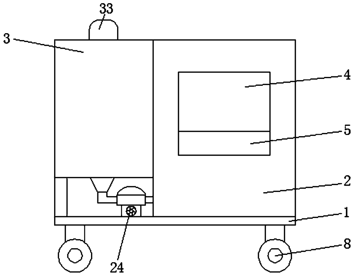
[0027] refer to Figure 1-7 , an automatic coating device for castings, including a base 1, the lower end of the base 1 is symmetrically provided with rollers 8, which can facilitate the overall movement of the device and facilitate the movement and transportation of the device.

[0028] The upper end of the base 1 is provided with a working box 2, and one side of the working box 2 is provided with a mixing device 3, and the mixing device 3 includes a paint box 31 fixedly connected with the working box 2, and both sides of the upper end of the paint box 31 are respectively provided with a liquid inlet Port 32, a stirring motor 33 is installed in the middle part of th...


PUM


Abstract

The invention relates to the technical field of spraying devices, in particular to an automatic casting coating spraying device which comprises a base, wherein a mixing device is arranged on one sideof a work box; a feeding device is arranged in a feeding hole; a guide plate is obliquely arranged in a discharging hole; two fluted discs are rotatably connected with the interior of a through groove; fixed devices are symmetrically arranged between the two fluted discs; a lead screw is rotatably connected between the lower parts of two partition boards through a bearing pedestal; a sliding seatis in screw joint with the outer side of the lead screw; a spraying mechanism is arranged at the upper end of the sliding seat; and the output shaft of a second motor penetrates through the partitionboards to be fixedly connected with the lead screw. The automatic casting coating spraying device is reasonable in structural design and convenient and fast to use, can mix coating uniformly and avoids sedimentation, ensures the casting spraying effect and also carries out air drying treatment on the castings to greatly improve the working efficiency and lower the labor intensity of a worker, hashigh practicality and deserves popularization.

Description

technical field [0001] The invention relates to the technical field of spraying devices, in particular to an automatic coating device for casting paint. Background technique [0002] At present, brushing paint is the main means to obtain good surface quality of castings. Commonly used paint application methods include spraying, brushing, dipping, etc. Spraying is often used for local application, which requires high paint quality and spraying equipment; brushing It is simple and easy to use and has a wide range of applications, but the interface quality of the coating is poor and it is the most difficult to control; dip coating is suitable for the outer surface of the inner core, and the quality is good. When it is used for the shell core, a large number of places that do not need coating are also coated, resulting in waste. [0003] The existing paint spraying method is usually to manually spray the paint on the surface of the casting with a spray gun. Due to the different...

Claims


Application Information

Patent Timeline
Patent Type & Authority Applications(China)
IPC IPC(8): B05B16/20B05B15/25B05B13/02B05B13/04
CPCB05B13/0221B05B13/0228B05B13/041B05B15/25B05B16/20
Inventor 段遵虎刘丽赵玉真
Owner 湖北省丹江口丹传汽车传动轴有限公司
Learn More