
Automatic clamping and positioning device for PCB

A technology for clamping and positioning PCB boards, which is applied in PCB positioning, circuit board tool positioning, electrical components and other directions during processing, and can solve the problems of PCB board accuracy that is prone to deviation, PCB board shaking and fixing instability, PCB board board positioning, etc. Damage and other problems, to achieve the effect of automatic clamping, improve safety and practicality, and improve the freedom of adjustment

Inactive Publication Date: 2018-11-13
黄永锋
View PDF0 Cites 13 Cited by
  • Summary
  • Abstract
  • Description
  • Claims
  • Application Information

AI Technical Summary

Problems solved by technology

[0003] However, the existing PCB circuit boards have some shortcomings in the process of clamping and clamping. There is no mechanism for clamping and protecting the PCB board during the process of clamping and fixing the PCB board, which will easily cause excessive clamping pressure. The PCB board is damaged, and it is easy to shake and fix the PCB board after clamping and other processing processes, resulting in low production and processing efficiency, and it is easy to shift, making the accuracy of PCB board production and processing not high.

Method used


Image

  • Automatic clamping and positioning device for PCB
  • Automatic clamping and positioning device for PCB
  • Automatic clamping and positioning device for PCB

Examples


Embodiment Construction

[0016] The following will clearly and completely describe the technical solutions in the embodiments of the present invention with reference to the accompanying drawings in the embodiments of the present invention. Obviously, the described embodiments are only some, not all, embodiments of the present invention. Based on the embodiments of the present invention, all other embodiments obtained by persons of ordinary skill in the art without making creative efforts belong to the protection scope of the present invention.

[0017] In the description of the present invention, it should be noted that the terms "center", "upper", "lower", "left", "right", "vertical", "horizontal", "inner", "outer" etc. The indicated orientation or positional relationship is based on the orientation or positional relationship shown in the drawings, and is only for the convenience of describing the present invention and simplifying the description, rather than indicating or implying that the referred d...


PUM


Abstract

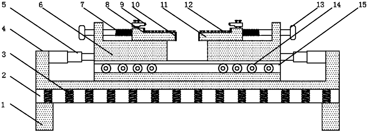
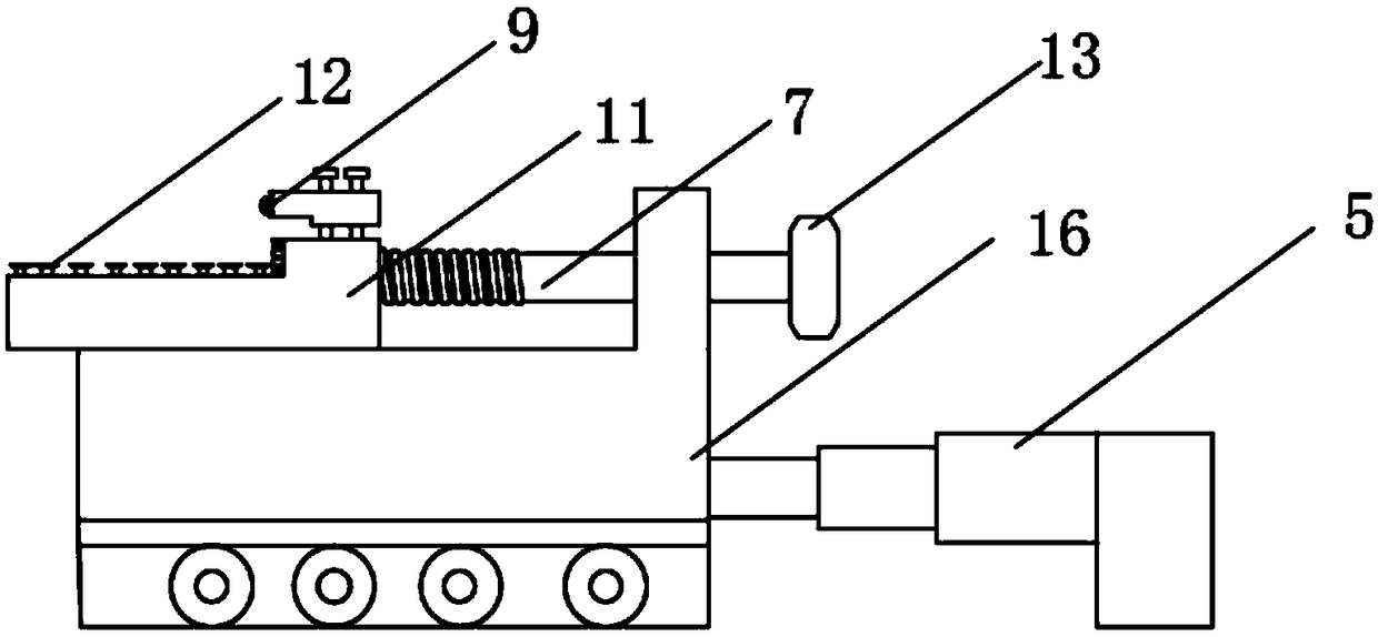
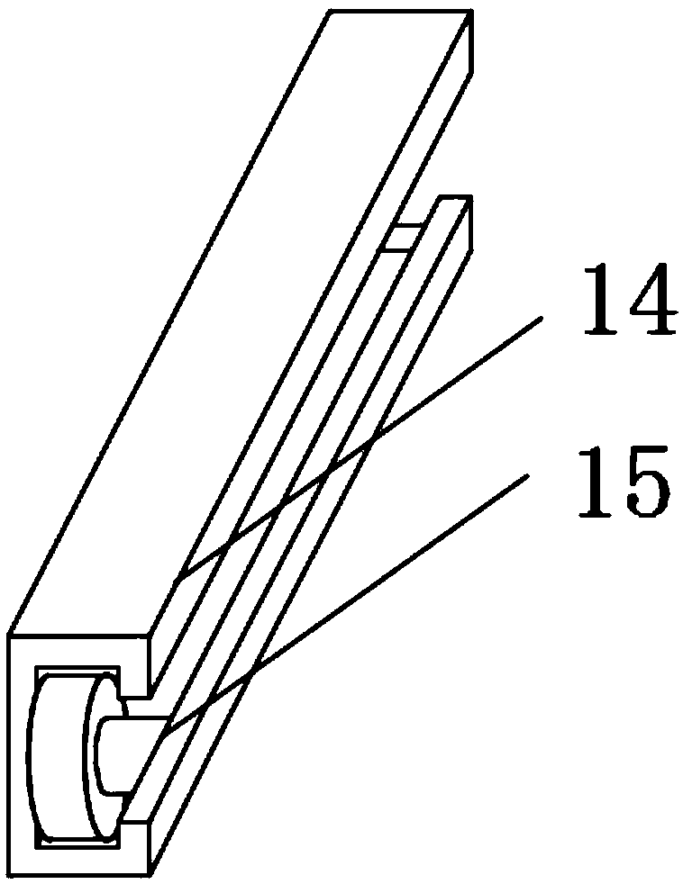
The invention discloses an automatic clamping and positioning device for a PCB. The automatic clamping and positioning device comprises a U-shaped base and a sliding block. A damping layer is arrangedat the surface of the bottom of the U-shaped base; and a damping spring is arranged inside the damping layer. Telescopic rods are arranged at the surfaces of the sides of the U-shaped base; a slidingblock is arranged at one end of each telescopic rod in a pushing manner; a sliding rail is arranged at the bottom of the sliding block; and sliding pulleys are arranged at one side of the sliding block inside the sliding rail in a sliding manner. According to the invention, the telescopic rods arranged at the two sides of the U-shaped base push the sliding blocks to slide in the sliding rail; andclamping blocks are driven by the sliding blocks to clamp and fix a PCB. Moreover, infrared on-off calibration sensors are used for carrying out automatic on-off calibration; if fine adjustment is needed, rotary knobs are adjusted to screw fine-adjustment screw rods to carry out fine adjustment, so that the adjustment freedom of the PCB is improved substantially and automatic clamping is realized; and the precision of PCB clamping is improved.

Description

technical field [0001] The invention relates to the technical field of PCB boards, in particular to a PCB board automatic clamping and positioning device. Background technique [0002] The Chinese name of PCB is printed circuit board, also known as printed circuit board. It is an important electronic component, a support for electronic components, and a carrier for electrical connections of electronic components. Because it is made by electronic printing, it is called a "printed" circuit board. Printed boards have developed from single-layer to double-sided, multi-layer and flexible, and still maintain their own development trends. Due to the continuous development in the direction of high precision, high density and high reliability, continuous reduction in size, cost reduction and performance improvement, printed boards still maintain strong vitality in the development of electronic equipment in the future. The discussion on the future development trend of printed board m...

Claims


Application Information

Patent Timeline
Patent Type & Authority Applications(China)
IPC IPC(8): H05K3/00
CPCH05K3/0008H05K2203/15
Inventor 黄永锋
Owner 黄永锋
Learn More