Workbench for de-bonding bonded sheet product and clamping method
A workbench, workbench technology, applied in electrical components, semiconductor/solid-state device manufacturing, circuits, etc., can solve the problems of reduced suction, inability to fully fit, ignoring small batch processing, etc., to avoid inconvenience and avoid positioning. Unstable, versatile effect
- Summary
- Abstract
- Description
- Claims
- Application Information
AI Technical Summary
Problems solved by technology
Method used
Image
Examples
Embodiment 1
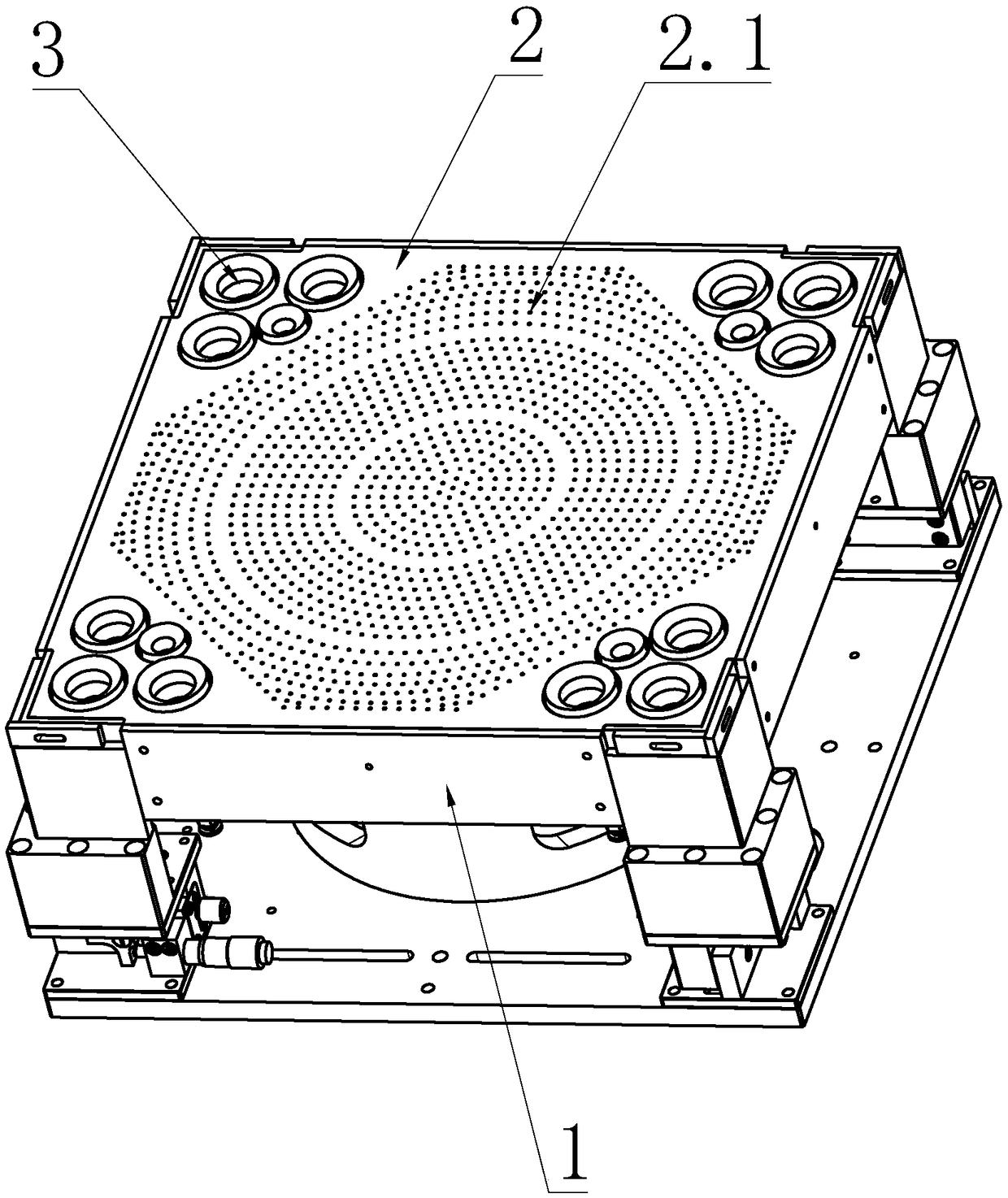
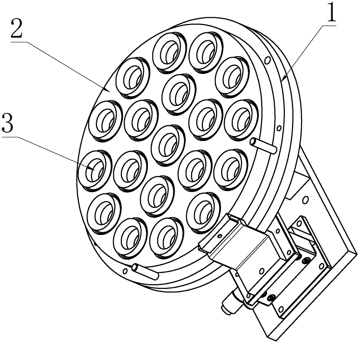
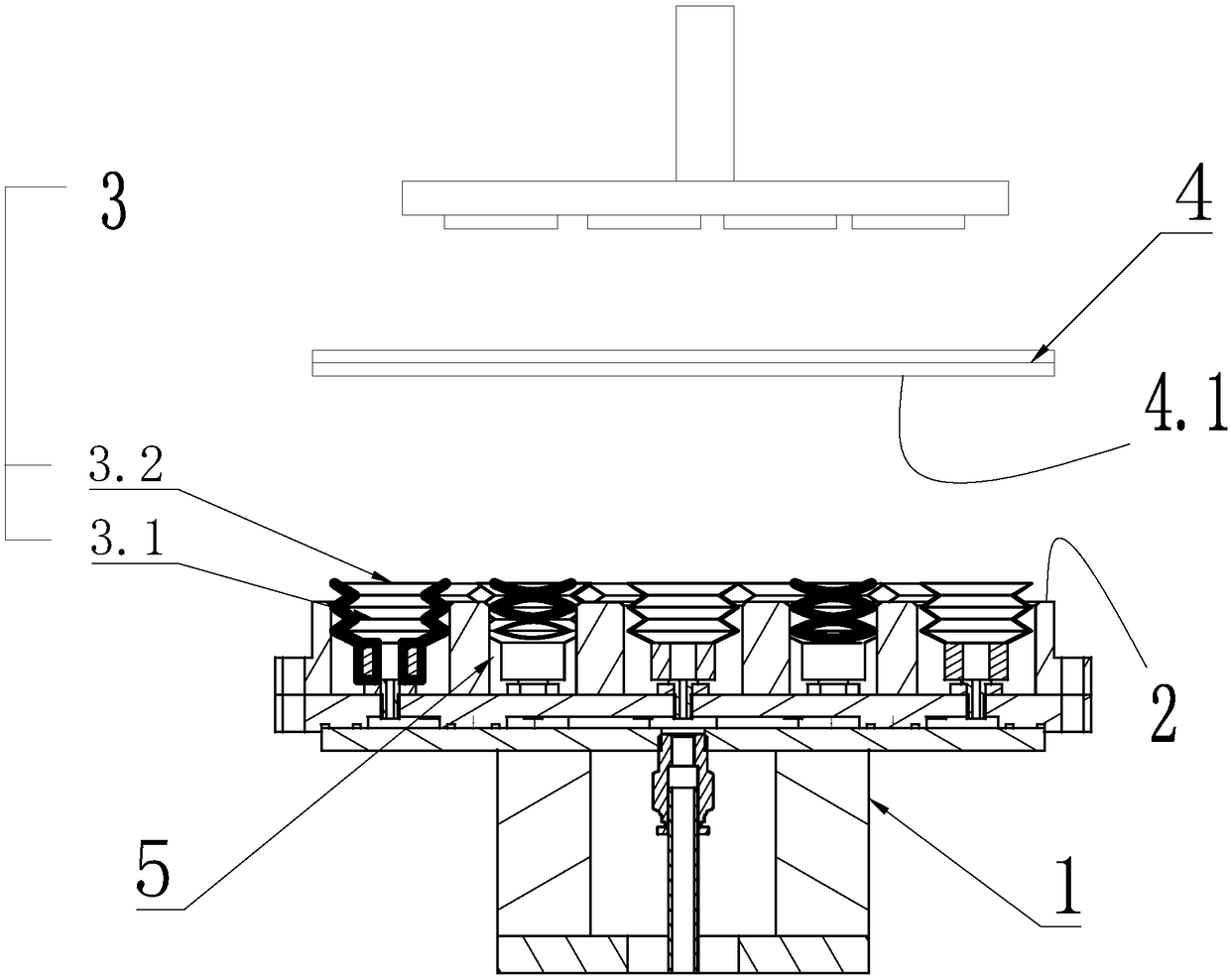
[0035] The invention provides a workbench for debonding after bonding of thin sheet products, which includes such as figure 1As shown in the carrier 1, the carrier 1 is placed in a horizontal direction as shown in the figure, and it is characterized in that: the carrier 1 is provided with a reference surface 2 and at least one suction cup group 3, when the product 4 is placed in the vertical direction When placed on the stage 1 from top to bottom, the suction cup group 3 touches the product 4 before the reference surface 2 and is attracted to the back side 4.1 of the product 4. In other words, the product 4 moves vertically from top to bottom. In the process of lowering, first touch the part of the suction cup group 3 above the carrier 1, and when the suction cup group 3 sucks the product, the suction cup group 3 drives the product 4 that is attracted to the suction cup group 3 to move toward the position of the reference surface 2 Until the rear side 4.1 of the product 4 abut...
Embodiment 2
[0039] The structure is basically the same as that of Embodiment 1, the difference is that the suction cup set 3 includes several vacuum suction nozzles 3.1 made of elastic material, and one end of the vacuum suction nozzles 3.1 along its own length direction is installed on the carrier 1 , the other end of the vacuum nozzle 3.1 is provided with an opening 3.2, which is used to attach to the back side 4.1 of the product 4. As mentioned above, when the vacuum suction nozzle 3.1 made of elastic material is used for the suction cup group 3, specifically, the corrugated suction nozzle can be used, and the suction force between the vacuum suction nozzle 3.1 and the back side 4.1 of the product 4 increases, At the same time, it also drives the product 4 along figure 1 The thickness direction of the middle stage 1 moves downward until the back of the product 4 is attached to the upper surface of the stage 1. Of course, if the stage 1 is provided with an additional reference surface 2...
Embodiment 3
[0041] The structure is basically the same as that of the second embodiment, the difference is that: the stage 1 is provided with a worktable, and the suction cup set 3 and the reference plane 2 are both located on the worktable of the stage 1 . Such as figure 1 As shown, the working table is the upper end surface of the carrier 1 , and the entire working table is used as the reference plane 2 as a whole. Certainly, the reference plane 2 may be an additional reference plate or a reference block independently provided on the worktable, or may be the upper end surface of the cutting platform 1 so that part of the worktable serves as the reference plane 2 .
PUM
 Abstract
Description
Claims
Application Information
 - R&D
- Intellectual Property
- Life Sciences
- Materials
- Tech Scout
- Unparalleled Data Quality
- Higher Quality Content
- 60% Fewer Hallucinations
Browse by: Latest US Patents, China's latest patents, Technical Efficacy Thesaurus, Application Domain, Technology Topic, Popular Technical Reports.
© 2025 PatSnap. All rights reserved.Legal|Privacy policy|Modern Slavery Act Transparency Statement|Sitemap|About US| Contact US: help@patsnap.com


