
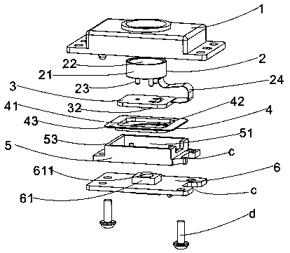
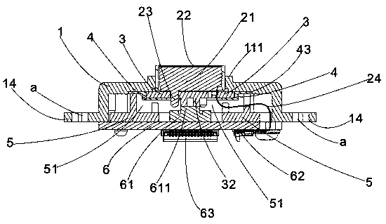
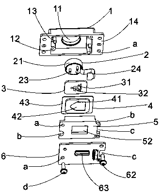
Overall structure of fingerprint recognition module and physical key

A fingerprint recognition module and overall structure technology, applied in character and pattern recognition, instruments, computer components, etc., can solve the problems of human resources and property loss, large space volume, large equipment volume, etc.

Pending Publication Date: 2018-11-13
张平
View PDF0 Cites 2 Cited by
  • Summary
  • Abstract
  • Description
  • Claims
  • Application Information

AI Technical Summary

Problems solved by technology

[0003] However, in the current fingerprint identification devices on the market, the fingerprint collection and identification module and the internal physical buttons are separated, and they are two parts with different functions. The fingerprint information collected by the fingerprint identification module is transmitted to the internal key switch through the transmission line. The key switch transmits the information to the host processing system through another transmission line for processing. There are many components inside the overall device, and there are many transmission lines. The space occupied by the device is large, which makes the entire device larger. If there is a problem with one of the transmission lines , it will lead to failure of information transmission, requiring experienced technicians to repair or directly scrap, resulting in loss of human resources and property. Therefore, the existing technology needs to be improved

Method used


Image

  • Overall structure of fingerprint recognition module and physical key
  • Overall structure of fingerprint recognition module and physical key
  • Overall structure of fingerprint recognition module and physical key

Examples


Embodiment Construction

[0018] The following will clearly and completely describe the technical solutions in the embodiments of the present invention with reference to the accompanying drawings in the embodiments of the present invention. Obviously, the described embodiments are only some, not all, embodiments of the present invention. Based on the embodiments of the present invention, all other embodiments obtained by persons of ordinary skill in the art without making creative efforts belong to the protection scope of the present invention.

[0019] see Figure 1-5 , the present invention provides a technical solution: an overall structure of a fingerprint identification module and physical buttons, including: a cover 1, a fingerprint module 2, a module pad 3, an elastic body 4, a pressing block 5, and a pcb board 6.

[0020] The upper cover 1 is hollow inside and has a certain height. The upper cover 1 is provided with an upper cover through hole 11 in the middle of the upper surface. The upper co...


PUM


Abstract

The invention discloses an overall structure of a fingerprint recognition module and a physical key. The overall structure comprises an upper cover, a fingerprint module, a module gasket, an elastomer, a pressing block and a pcb. The overall structure is characterized in that the elastomer is arranged, the pressing side of the elastomer is arranged on the frame of the pressing block, the module gasket is arranged in the groove of the elastomer, the pressing block and the pcb fix and press the pressing side of the elastomer on the top part in the upper cover, the elastomer seals the module table and the module gasket on the top part in the upper cover and only the fingerprint acquisition mirror is exposed out of the through hole of the upper cover. The touch column of the lower bottom surface of the module gasket contacts the flexible key cap of the key switch on the pcb through the through hole of the elastomer and the through hole of the pressing block so that the combined structure of the fingerprint module and the physical key can be integrally formed, the volume in the equipment space is small, the fingerprint module component is sealed on the top part in the upper cover and thus the waterproof and dustproof performance of the fingerprint component can be realized and the service life of the fingerprint module can be enhanced.

Description

technical field [0001] The invention relates to the fingerprint identification industry, in particular to a combined structure of a fingerprint identification module and a button. Background technique [0002] Since each person's fingerprint has lifelong invariance, uniqueness and convenience, fingerprints have almost become synonymous with biometric identification and are used to identify each person. In today's life, the application technology of fingerprint recognition involves many disciplines such as image processing, pattern recognition, computer vision, wavelet analysis, etc., and fingerprint recognition has been widely used in people's daily life. Such as fingerprint access control, fingerprint lock, fingerprint attendance machine, computer fingerprint recognition, mobile phone fingerprint recognition, bank payment, etc. In fingerprint recognition, the user only needs to put his finger on a fixed fingerprint collection place, and the fingerprint module reads the data...

Claims


Application Information

Patent Timeline
Patent Type & Authority Applications(China)
IPC IPC(8): G06K9/00
CPCG06V40/13
Inventor 张平
Owner 张平
Learn More