Friction welding equipment

A technology of friction welding and equipment, which is applied in the field of friction welding, can solve the problems of waste of manpower and material resources, and achieve the effects of high degree of automation, easy use, and simple device structure

Inactive Publication Date: 2018-11-13
潘育素
View PDF0 Cites 0 Cited by
  • Summary
  • Abstract
  • Description
  • Claims
  • Application Information

AI Technical Summary

Problems solved by technology

[0002] At present, friction welding technology is used in many industrial fields, but most of the current friction welding equipment can only be used for a small number of regular-sized parts. For irregular parts, separate molds or separate machines are required, resulting in waste of manpower and material resources. Propose this friction welding invention equipment for the above problems

Method used


Image

  • Friction welding equipment
  • Friction welding equipment
  • Friction welding equipment

Examples


Embodiment Construction

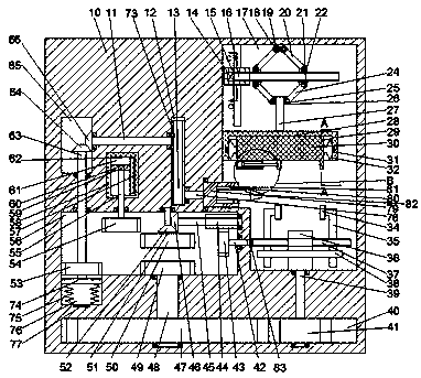
[0018] like figure 1As shown, a friction welding equipment of the present invention includes a frame 10, a first hydraulic tank 58 is arranged inside the frame 10, a first hydraulic chamber 61 is arranged inside the first hydraulic tank 58, and a first hydraulic chamber 61 is arranged inside the first hydraulic tank 58. The right side of a hydraulic chamber 61 is provided with the first hydraulic pipe 62 communicating with the upper and lower ends, the first hydraulic pipe 62 is fixed with 57, the first hydraulic chamber 61 is slidably provided with 60, and the 60 is fixed with 60 There is a first motor 59, and the first motor 59 is power-connected with a 55. The frame 10 is provided with a first gear chamber 56, and the lower end surface of the 55 is arranged in the first gear chamber 56. The lower end surface of a gear chamber 56 is fixedly provided with a first straight gear 54, and the upper side of the first gear chamber 56 is provided with a second gear chamber 65 locate...


PUM


Abstract

The invention discloses friction welding equipment. The friction welding equipment comprises a rack; a first hydraulic tank is arranged inside the rack; a first hydraulic chamber is arranged inside the first hydraulic tank; the right side of the first hydraulic chamber is provided with a first hydraulic pipe which communicates with the upper and lower ends of a part; the first hydraulic pipe is internally and fixedly provided with a part; a part is slidably arranged inside the first hydraulic chamber; a first motor is fixedly arranged inside a part; the first motor is in power connection witha part; a first gear chamber is arranged inside the rack; the lower end face is arranged inside the first gear chamber; the lower end face of the first gear chamber is fixedly provided with a first straight gear; the upper side of the first gear chamber is provided with a second gear chamber positioned inside the rack; a first rotating shaft is rotationally arranged between the second gear chamberand the first gear chamber; and a first rotating shaft positioned inside the first gear chamber is fixedly provided with a part.

Description

technical field [0001] The invention relates to the technical field of friction welding, in particular to a friction welding equipment. Background technique [0002] At present, friction welding technology is used in many industrial fields, but most of the current friction welding equipment can only be used for a small number of regular-sized parts. For irregular parts, separate molds or separate machines are required, resulting in waste of manpower and material resources. Propose this friction welding invention equipment for the above problems. Contents of the invention [0003] Aiming at the deficiencies of the above technologies, the present invention proposes a friction welding equipment. [0004] A kind of friction welding equipment of the present invention comprises a frame, a first hydraulic tank is provided in the frame, a first hydraulic chamber is provided in the first hydraulic tank, and the right side of the first hydraulic chamber is provided with The first ...

Claims


Application Information

Patent Timeline
Patent Type & Authority Applications(China)
IPC IPC(8): B23P23/04B23K20/12B23K20/26B23K37/04B23K37/053B23K37/08
CPCB23P23/04B23K20/125B23K20/126B23K37/08
Inventor 潘育素
Owner 潘育素
Why Eureka
Try Eureka