Washing device for washing gear shaft

A technology for cleaning devices and gear shafts, applied in the direction of liquid cleaning methods, dry gas arrangement, cleaning methods and appliances, etc., can solve the problems of reduced work efficiency, complicated cleaning process, high labor cost, etc., to ensure speed and efficiency, Improve the cleaning effect and improve the effect of cleaning area

Inactive Publication Date: 2018-11-13
NANTONG ZHONGLV GEAR CO LTD
View PDF1 Cites 2 Cited by
  • Summary
  • Abstract
  • Description
  • Claims
  • Application Information

AI Technical Summary

Problems solved by technology

The current cleaning of the gear shaft generally uses a high-pressure spray gun to clean the surface of the gear shaft, but the cleaning process is relatively complicated, and special personnel are required to be responsible for cleaning. The workload is large, the cleaning efficiency is low, and the labor cost is high. The surface humidity of the gear shaft after cleaning Higher, takes time to dry
[0003] Patent No. 201621292674.4 The cleaning device for flushing gears solves the above problems, but has the following disadvantages: 1. It needs to be manually unloaded, and the cleaning work of the entire cleaning device needs to be stopped when a batch of gear shafts are unloaded, and the next batch of gear shafts needs to be cleaned. After the last batch of gear shafts is finished, the cleaning work will be carried out, which will reduce the work efficiency; 2. The part of the gear shaft to be cleaned is not the entire surface of the gear shaft, and the cleaning is not thorough; 3. The drying effect of the surface of the gear shaft after cleaning is poor

Method used


Image

  • Washing device for washing gear shaft
  • Washing device for washing gear shaft

Examples


Embodiment approach

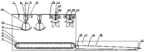
[0019] Such as figure 1 An embodiment of a cleaning device for cleaning gear shafts of the present invention is shown, including

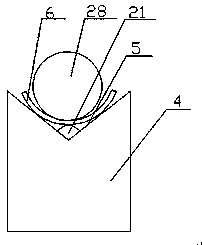
[0020] A transmission mechanism, the transmission mechanism includes a bracket 1, two rolling chains 2 arranged one behind the other in the bracket 1, the rolling chain 2 and the bracket 1 are flexibly connected by a rotating shaft 3, and the rolling chain 2 follows the movement of the rotating shaft 3 Rotate and rotate, the outer end of the rolling chain 2 is provided with a plurality of transmission groups arranged at equal intervals, the extension direction of the transmission group is vertical to the transmission direction of the rolling chain 2, and the transmission groups on the two rolling chains 2 are arranged correspondingly in turn, Such as figure 2 As shown, the transmission group includes a transmission plate 4, the upper end surface of the transmission plate 4 is an inwardly recessed notch 5, and the transmission plate 4 of the two c...


PUM


Abstract

The invention relates to a washing device for washing a gear shaft. The washing device comprises a transmission mechanism, a spray washing mechanism, an air drying mechanism and a discharging mechanism, wherein the transmission mechanism comprises a bracket and two rolling chains arranged in the bracket back and forth, a plurality of transmission groups arranged at equal intervals are arranged atthe outer side end of each rolling chain, and each transmission group comprises a transmission plate, and a concave opening which is depressed inwards is formed in the upper end surface of each transmission plate; the spray washing mechanism comprises a plurality of spray washing groups evenly arranged and an inductor placed at the position, close to the spray washing groups, on the upper portionof the interior of the bracket; the air drying mechanism is placed at a track group on the upper portion of the interior of the bracket, the track group consists of two tracks, and an air drying groupis arranged on each track; and the discharging mechanism comprises a glass reinforced plastic fiber conveying belt and a discharging shell placed on the outer side of the glass reinforced plastic fiber conveying belt, and a plurality of glass reinforced plastic fiber shaft rods longitudinally arranged are arranged above the glass reinforced plastic fiber conveying belt. The washing device has theadvantages of being convenient to discharge and thorough in washing and improving the drying effect.

Description

Technical field: [0001] The invention relates to a cleaning device for cleaning a gear shaft. Background technique: [0002] The gear shaft is a precision hardware part. During the processing and production of the gear shaft, the parts need to go through the processing steps from the blank to the finished product, such as turning, cutting, drilling, grinding, milling, etc. The parts are processed enough, and the surface and There are many impurities such as oil stains and debris in the hole, which will affect the further processing and use of the parts and need to be cleaned. Existing cleaning of the gear shaft generally uses a high-pressure spray gun to clean the surface of the gear shaft, but the cleaning process is relatively complicated, and special personnel are required to be responsible for cleaning, the workload is large, the cleaning efficiency is low, the labor cost is high, and the surface humidity of the gear shaft after cleaning Higher and takes time to dry. ...

Claims


Application Information

Patent Timeline
Patent Type & Authority Applications(China)
IPC IPC(8): B08B3/02B08B13/00F26B21/00
CPCB08B3/022B08B13/00F26B21/004
Inventor 潘志进
Owner NANTONG ZHONGLV GEAR CO LTD
Why Eureka
Try Eureka