
Aerator impeller

An aerator and impeller technology, applied in fish farming, application, animal husbandry, etc., can solve the problems of poor aeration effect, inability to replace leaves, and high density of seedlings, so as to facilitate water breaking, improve oxygenation effect, The effect of improving strength and toughness

Pending Publication Date: 2018-11-13
台州旺发机电股份有限公司
View PDF10 Cites 0 Cited by
  • Summary
  • Abstract
  • Description
  • Claims
  • Application Information

AI Technical Summary

Problems solved by technology

[0002] With the continuous development of my country's aquaculture industry and the continuous improvement of consumers' purchasing power of fish food, the contradiction between supply and demand continues to increase. At this time, it is necessary to breed more seedlings in ponds with a fixed area. Oxygen-increasing pumps have become an indispensable oxygen-increasing equipment for existing aquaculture. Aerators are important equipment for aquaculture in my country, and impeller-type aerators are the most widely used in various aerators. The impeller of the impeller type aerator is the key component of the aerator. At present, the impellers of the traditional impeller aerator mainly include iron impeller and plastic impeller. The iron impeller is expensive to manufacture and is easy to corrode. The existing plastic impeller It is widely used due to its light weight, corrosion resistance, and high production efficiency. However, most of the existing plastic impellers are integrally injection-molded, and the blades and sealing floats are integrated. The patent of "plastic impeller" has a single form in the actual use process, and it is impossible to replace the blades according to the actual oxygen increase needs. In actual use, the blades are relatively weaker than the impellers, and the blades are easier to damage, resulting in poor oxygen increase effect.

Method used


Image

  • Aerator impeller
  • Aerator impeller
  • Aerator impeller

Examples


Embodiment Construction

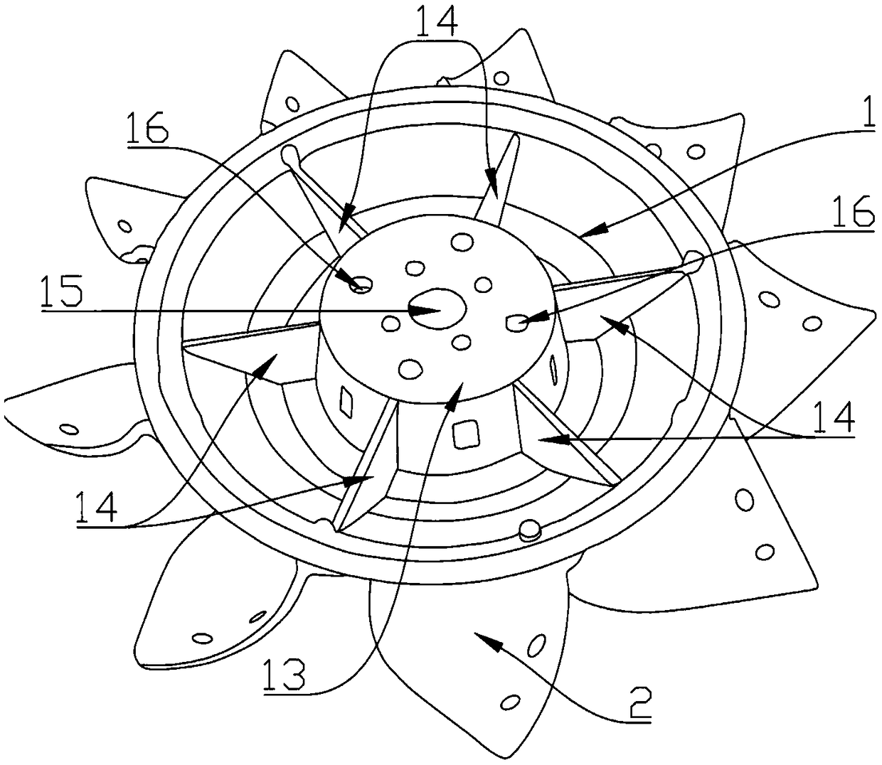
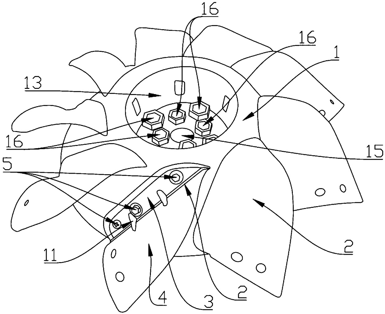
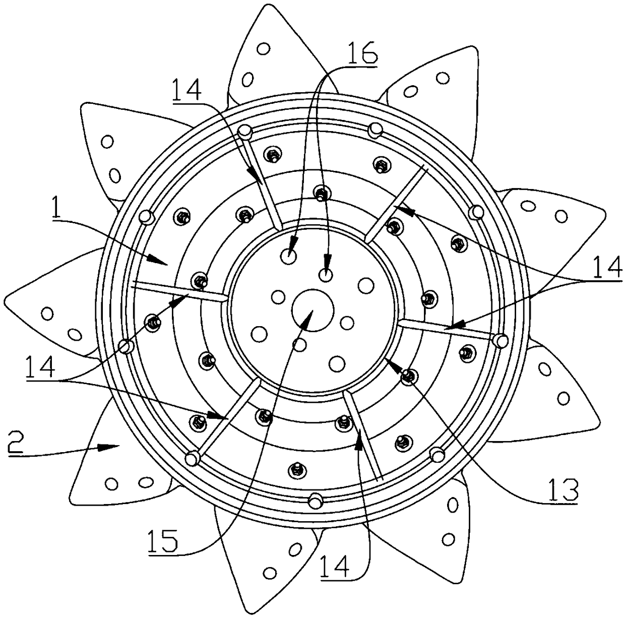
[0028] Below in conjunction with accompanying drawing, the present invention will be further described with specific embodiment, see Figure 1-8 :

[0029] An aerator impeller, comprising a wheel body 1 and several wheel pieces 2, the shape of the wheel body 1 is spherical, and the wheel pieces 2 are evenly distributed on the outer periphery of the wheel body 1; the wheel pieces 2 It includes a fixed piece 3 and a water-draining piece 4. The surface of the fixed piece 3 is arc-shaped and matches the arc surface of the wheel body 1. The fixed piece 3 is detachably connected to the wheel body 1. The dial The shape of the water-repellent sheet 4 is a curved surface, and one end of the water-repellent sheet 4 is provided with a water raising part 6 , and the other end of the water-repellent sheet 4 is provided with a water-lifting part 7 .

[0030] The wheel piece 2 of the present invention is detachably connected to the wheel body 1, and different wheel pieces 2 can be selected ...


PUM


Abstract

The invention relates to the technical field of aquaculture aeration and particularly relates to an aerator impeller. The aerator impeller comprises an impeller body and a plurality of impeller pieces, wherein the impeller body is of a spherical surface form, the impeller pieces are uniformly distributed on the periphery of the impeller body and comprise fixed pieces and water stirring pieces, thesurfaces of the fixed pieces are arc-shaped and are matched with an arc surface of the impeller body, and the fixed pieces are detachably connected with the impeller body through a fastening component; the water stirring pieces are respectively of a curved surface, water raising parts are arranged at one ends of the water stirring pieces, and water pumping parts are arranged at the other ends ofthe water stirring pieces. The impeller pieces and the impeller body are detachably connected, different impeller pieces can be selected to be matched with the impeller body according to the practicalaeration, water plough and surging requirements, the impeller pieces are always damaged and worn in the long rotation process, and the aeration effect is worsen; and by changing the impeller pieces,the cost is relatively low, the optimal performance of the aerator is restored, and the service life of the aerator is prolonged, so that the aerator impeller is suitable for being widely used.

Description

technical field [0001] The invention relates to the technical field of aquaculture aeration equipment, in particular to an aerator impeller. Background technique [0002] With the continuous development of my country's aquaculture industry and the continuous improvement of consumers' purchasing power of fish food, the contradiction between supply and demand continues to increase. At this time, it is necessary to breed more seedlings in ponds with a fixed area. Oxygen-increasing pumps have become an indispensable oxygen-increasing equipment for existing aquaculture. Aerators are important equipment for aquaculture in my country, and impeller-type aerators are the most widely used in various aerators. The impeller of the impeller type aerator is the key component of the aerator. At present, the impellers of the traditional impeller aerator mainly include iron impeller and plastic impeller. The iron impeller is expensive to manufacture and is easy to corrode. The existing plastic...

Claims


Application Information

Patent Timeline
Patent Type & Authority Applications(China)
IPC IPC(8): A01K63/04
CPCA01K63/042
Inventor 王云志
Owner 台州旺发机电股份有限公司
Learn More