a stable motor
A stable, chassis technology, applied in the direction of electromechanical devices, electrical components, electric components, etc., can solve the problems of high vibration intensity of the motor, severe vibration of the end cover, poor motor stability, etc., to achieve low vibration frequency, increase vibration frequency, Good sealing effect
- Summary
- Abstract
- Description
- Claims
- Application Information
AI Technical Summary
Problems solved by technology
Method used
Image
Examples
Embodiment 1
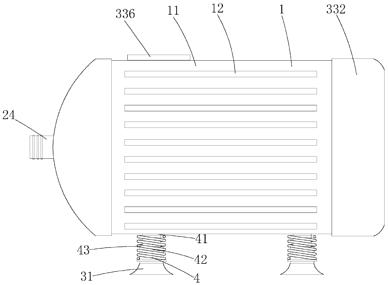
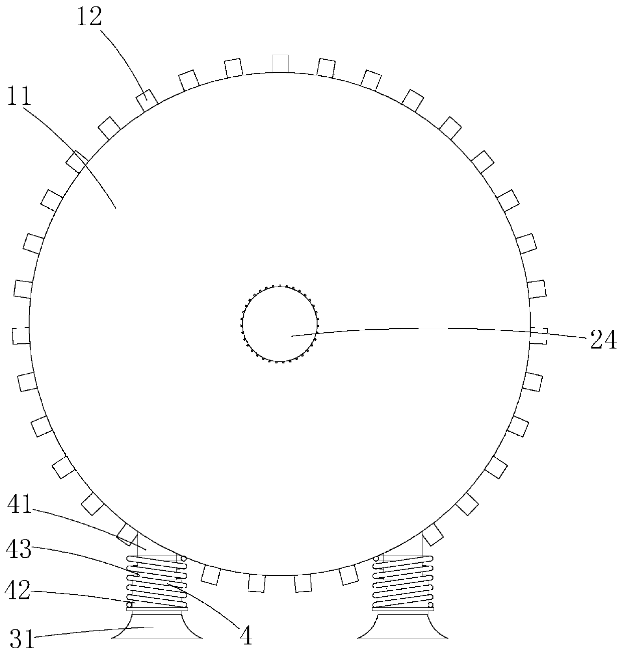
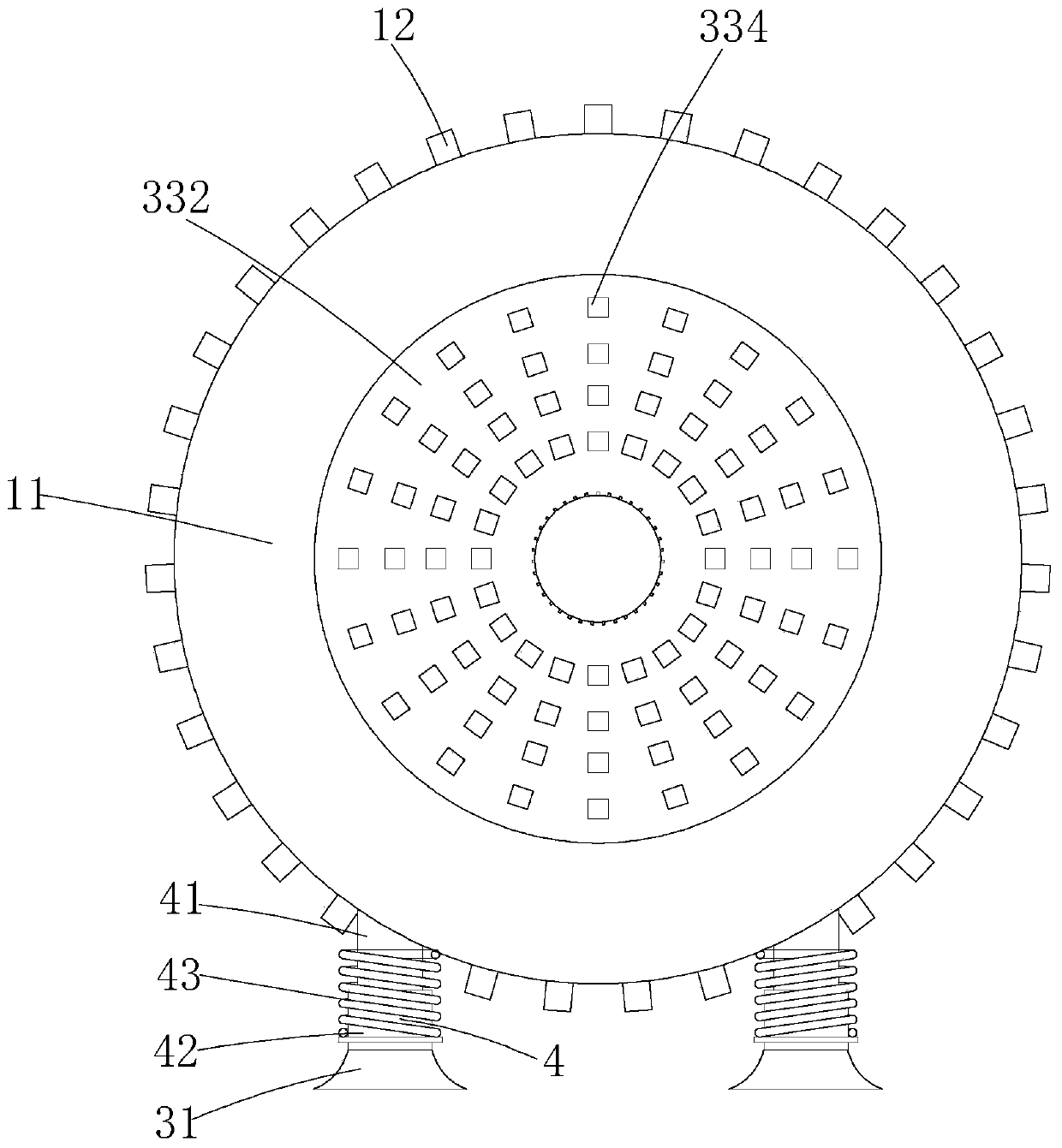
[0041] Such as Figure 1-11 As shown, a stable motor includes a casing 1, a rotating core part 2, a fixing device 3, a supporting part 4 and a sealing structure 5, wherein the casing 1 includes a casing 11 and a heat sink 12, and the casing The body 11 is a metal cylinder, the heat sink 12 is a metal sheet, and the heat sink 12 is fixed on the outer wall of the housing 11; the rotating core part 2 is arranged in the housing 11, and the rotating core part 2 Including rotor 21, stator winding 22, stator iron core 23 and rotating shaft 24, described rotor 21, stator winding 22 and stator iron core 23 are the rotor, stator winding and stator iron in the motor with high stability in the existing market. Core, its specific matching method is also the same as the existing high-stability motors on the market, and its specific details will not be repeated; the fixing device 2 is to fix the housing 11 by suction, and the fixing device 2 3. It includes a suction cup 31 and a heat dissip...
Embodiment 2
[0051] Such as Figure 12-15 As shown, the difference between this implementation and Embodiment 1 is that this embodiment increases the cooperation of the water cooling component 6 and the heat dissipation component, thereby improving the heat dissipation effect of the entire motor. Specifically: the water cooling component 6 can perform water circulation to improve The heat dissipation effect of the housing 11; the water cooling component 6 includes a water cooling chamber 61, a water inlet pipe 62, an outlet pipe 63, a drainage branch pipe 64, a water tank 67 and a pump body 68 arranged on the housing 11, and the water cooling The cavity 61 is a cavity provided outside the housing 11, the water inlet pipe 62 is a metal pipe, the water inlet pipe 62 communicates with the water cooling chamber 61, and one end of the water inlet pipe 62 is connected to the pump The pump body 68 is connected to each other, and the pump body 68 is a water pump; the described water tank 67 is a p...
Embodiment 3
[0054] Such as Figure 16-18 As shown, the difference between this embodiment and Embodiment 1 is that this embodiment discloses an end cover component 7 connected to the casing, specifically: the end cover component 7 includes an end cover 71, a shock absorber 72 and a through hole 73, the end cover 71 is a metal cover, the end cover 71 is detachably connected to the housing 11, the number of shock absorbers 72 is three, and the three shock absorbers 72 are welded on the inner wall of the end cover 71 Above, the damping block 72 is a metal block; the through hole 73 is a circular through hole, and the rotating shaft 24 can pass through the through hole 73; the first convex edge 710 is welded in a circle The metal outer ring on the end cover 71 is recessed to one side on the side wall of the first convex edge 710 to form a circle of concave ring. The concave ring is an insertion concave part 711. The second protruding edge 110 is also a metal ring, and the second protruding e...
PUM
 Abstract
Description
Claims
Application Information
 - R&D
- Intellectual Property
- Life Sciences
- Materials
- Tech Scout
- Unparalleled Data Quality
- Higher Quality Content
- 60% Fewer Hallucinations
Browse by: Latest US Patents, China's latest patents, Technical Efficacy Thesaurus, Application Domain, Technology Topic, Popular Technical Reports.
© 2025 PatSnap. All rights reserved.Legal|Privacy policy|Modern Slavery Act Transparency Statement|Sitemap|About US| Contact US: help@patsnap.com


