Method and device for detecting wave plate surface phase delay amount
A technology of phase delay and detection method, which is applied in the field of optical detection, can solve the problems such as the inability to detect the phase delay of the wave plate plane, and achieve the effect of simple operation process and high measurement accuracy
- Summary
- Abstract
- Description
- Claims
- Application Information
AI Technical Summary
Problems solved by technology
Method used
Image


Examples
Embodiment 1
[0034] The present embodiment provides a method for detecting the phase delay of the wave plate surface, which is used to detect the phase delay of each point on the surface of the wave plate 6 to be tested, including the following steps:
[0035] Using ZYGO interferometer 1 to generate plane light waves;
[0036] The plane light wave is first processed into a linearly polarized light wave, and the linearly polarized light wave is adjusted to a beam aperture to obtain a polarized light wave with a limited beam aperture, and the polarized light wave with a limited beam aperture is irradiated onto the wave plate 6 to be measured;
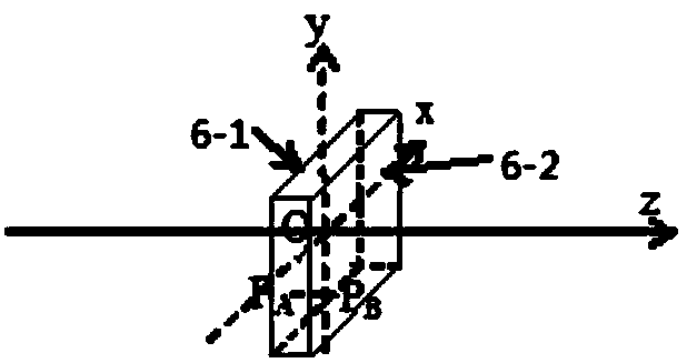
[0037] The wave plate 6 to be tested includes a first surface 6-1 and a second surface 6-2, adjusting the position of the ZYGO interferometer 1 and the wave plate 6 to be measured makes the reflected spot and plane of the first surface 6-1 The reflected light spots of the light waves coincide, and the positions of the ZYGO interferometer 1 and the wav...
Embodiment 2
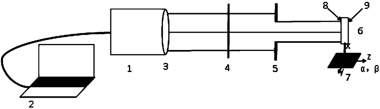
[0040] On the basis of Example 1, such as figure 1 , 2 As shown, the required components of the method provided by Embodiment 1 include: ZYGO interferometer 1, computer 2, polarizer 4, adjustable diaphragm 5, wave plate to be measured 6 and five-dimensional adjustment frame 7, the computer 2 It is electrically connected with the ZYGO interferometer 1, and the ZYGO interferometer 1 is provided with a standard lens 3, and the standard lens 3 is used to generate a plane light wave, and a polarizer 4, an adjustable optical Diaphragm 5 and the wave plate 6 to be tested, wherein the wave plate 6 to be tested is fixed by a five-dimensional adjustment frame 7;
[0041] The five-dimensional adjustment frame 7 can adjust the wave plate 6 to be tested in five directions: X-axis, Y-axis, Z-axis, pitch angle α and tilt angle β, wherein the X-axis is the level of the plane perpendicular to the optical axis of the plane light wave direction, the Y axis is the vertical direction of the plan...
Embodiment 3
[0060] This embodiment provides a detection device for the phase delay of the wave plate surface, such as figure 1 ,include:
[0061] ZYGO interferometer 1, computer 2, polarizer 4, adjustable aperture 5, wave plate to be measured 6 and five-dimensional adjustment frame 7, the computer 2 is electrically connected to the ZYGO interferometer 1, and the ZYGO interferometer 1 is set There is a standard lens 3, and the standard lens 3 is used to generate a plane light wave, and a polarizer 4, an adjustable diaphragm 5, and a wave plate to be measured 6 are sequentially arranged along the propagation direction of the plane light wave, wherein the wave plate to be measured 6 passes through Five-dimensional adjustment frame 7 is fixed;
[0062] The five-dimensional adjustment frame 7 can adjust the wave plate 6 to be tested in five directions: X-axis, Y-axis, Z-axis, pitch angle α and tilt angle β, wherein the X-axis is the level of the plane perpendicular to the optical axis of the ...
PUM
 Abstract
Description
Claims
Application Information
 - Generate Ideas
- Intellectual Property
- Life Sciences
- Materials
- Tech Scout
- Unparalleled Data Quality
- Higher Quality Content
- 60% Fewer Hallucinations
Browse by: Latest US Patents, China's latest patents, Technical Efficacy Thesaurus, Application Domain, Technology Topic, Popular Technical Reports.
© 2025 PatSnap. All rights reserved.Legal|Privacy policy|Modern Slavery Act Transparency Statement|Sitemap|About US| Contact US: help@patsnap.com