
Determination method of bridge influence line when vehicle passes at non-uniform speed

A measurement method and technology of influence lines, which are applied in the field of measurement of bridge influence lines when vehicles pass at non-uniform speeds, can solve problems such as passing bridges at a uniform speed, inability to accurately guarantee vehicles, and ill-posed solution equations of bridge influence lines, etc., to achieve accurate solutions and improve The effect of practicality

Active Publication Date: 2018-11-06
JSTI GRP CO LTD
View PDF8 Cites 11 Cited by
  • Summary
  • Abstract
  • Description
  • Claims
  • Application Information

AI Technical Summary

Problems solved by technology

[0003] In view of the above problems, the present invention proposes a method for measuring bridge influence lines when vehicles pass at non-uniform speeds. On the one hand, it solves the problem that vehicles cannot accurately ensure that vehicles pass through bridges at a uniform speed in actual tests, and on the other hand, it solves the discomfort of solving equations for bridge influence lines. problem, so as to obtain a more accurate bridge influence line

Method used


Image

  • Determination method of bridge influence line when vehicle passes at non-uniform speed
  • Determination method of bridge influence line when vehicle passes at non-uniform speed
  • Determination method of bridge influence line when vehicle passes at non-uniform speed

Examples


Embodiment Construction

[0059] In order to make the object, technical solution and advantages of the present invention more clear, the present invention will be further described in detail below in conjunction with the examples. It should be understood that the specific embodiments described here are only used to explain the present invention, not to limit the present invention.

[0060] The application principle of the present invention will be described in detail below in conjunction with the accompanying drawings.

[0061] In order to solve the problems in the prior art, such as complex calculation, non-unique identified influence lines, and unguaranteed accuracy, the present invention proposes a method for measuring bridge influence lines when vehicles pass at non-uniform speeds. The problem of ensuring that vehicles pass the bridge at a constant speed, on the other hand, solves the ill-posed problem of the solution equation of the bridge influence line, so as to obtain a more accurate bridge inf...


PUM


Abstract

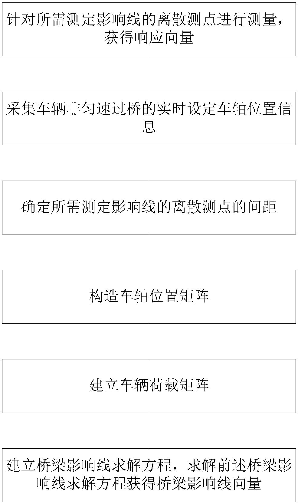
The invention discloses a determination method of a bridge influence line when a vehicle passes at a non-uniform speed. The determination method of a bridge influence line when a vehicle passes at a non-uniform speed includes the steps: 1) acquiring response vectors of discrete measuring points of a determination influence line as needed; 2) collecting the real-time axle positional information when the vehicle passes a bridge at a non-uniform speed; 3) determining the space between the discrete measuring points of the determination influence line as needed; 4) establishing a position solutionequation of the corresponding set axle every time when collecting response, obtaining the position vector of the corrected set axle, and constructing an axle position matrix; 5) based on the axle position matrix in the step 4), establishing a vehicle load matrix; and 6) based on the response vector and the vehicle load matrix, establishing an equation, and solving the equation to obtain the bridgeinfluence line vector. The determination method of a bridge influence line when a vehicle passes at a non-uniform speed solves the problem that a traditional determination method cannot guarantee that the vehicle can pass the bridge at a uniform speed in the actual test, and solves the ill-posed problem of the bridge influence line solution equation, thus obtaining a more accurate bridge influence line.

Description

technical field [0001] The invention belongs to the technical field of civil engineering applications, and in particular relates to a method for measuring bridge influence lines when vehicles pass at non-uniform speeds. Background technique [0002] The influence line is an inherent characteristic of the bridge, with clear physical meaning and rich local information of the bridge. The measurement influence line is often included in the bridge completion experiment of the new bridge and the inspection and evaluation of the old bridge. Based on the measured results of influence lines, the rapid detection of bridge bearing capacity can be further realized. Therefore, accurate determination of the actual influence line of the bridge has important engineering application value. At present, domestic and foreign scholars have carried out some research work on the measurement method of bridge influence line. The Chinese invention patent with the notification number CN104819813B pr...

Claims


Application Information

Patent Timeline
Patent Type & Authority Applications(China)
IPC IPC(8): G01M5/00
CPCG01M5/0008
Inventor 孙震应旭永徐一超
Owner JSTI GRP CO LTD
Learn More