3D measurement system of surface shape based on ray tracing
A ray tracing and three-dimensional measurement technology, applied in measurement devices, optical devices, instruments, etc., can solve the problems of difficult to measure optical surfaces with large curvature, difficult to compare and analyze design models, and increase the measurement range. , Increase the measurement slope and curvature range, and improve the effect of the applicable range
- Summary
- Abstract
- Description
- Claims
- Application Information
AI Technical Summary
Problems solved by technology
Method used
Image

Examples
Embodiment 1
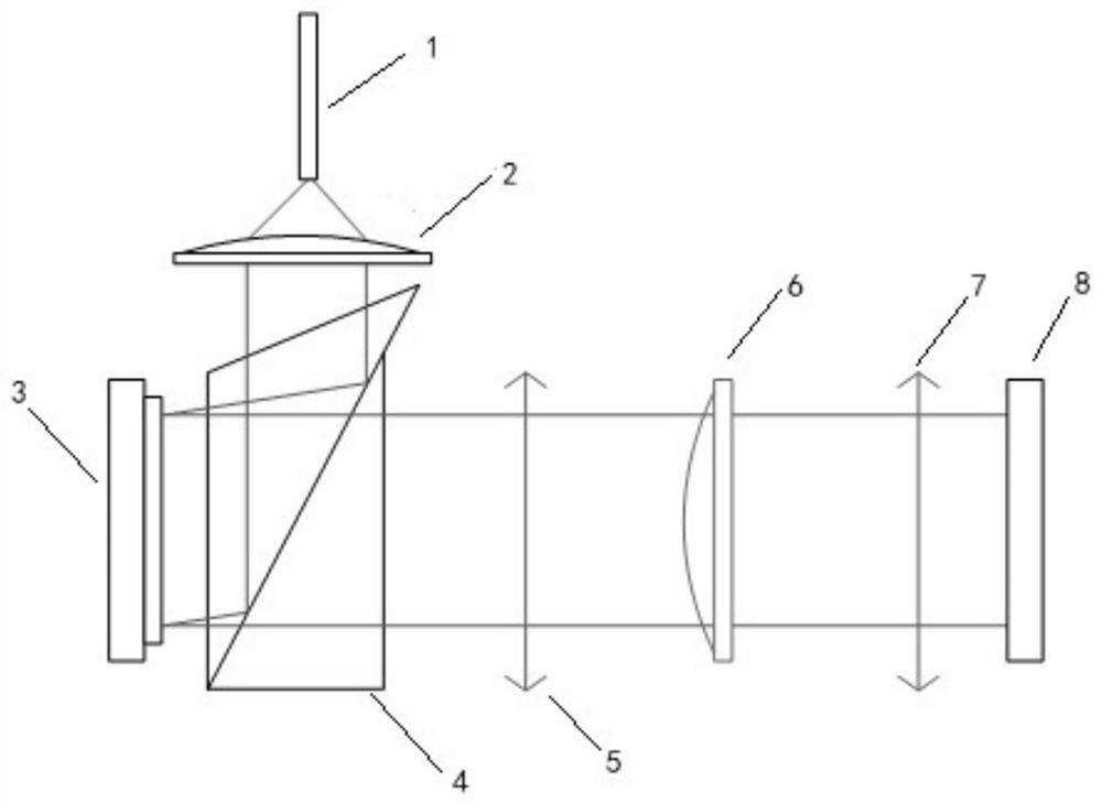
[0041]see figure 1 , a ray tracing surface shape three-dimensional measurement system of the present invention measures transmitted samples, including a light source, a shaping and collimating lens, a micro-mirror array DMD, a TIR prism, a lens group, a sample to be measured, a lens and a precision motion mechanism The detector CCD. The system is based on the ray tracing principle and the light field representation method to obtain the wavefront information of the transmitted sample.
[0042] To build the graphic system, first remove the sample to be tested, use the computer to control the light source and the micro-mirror array DMD, encode the incident light with structured light, and control the detector CCD to move along the direction of the main light through a precise motion mechanism to obtain the position of the incident light , angle and light intensity information to complete the system calibration; place the sample to be tested at the measurement position, control t...
Embodiment 2
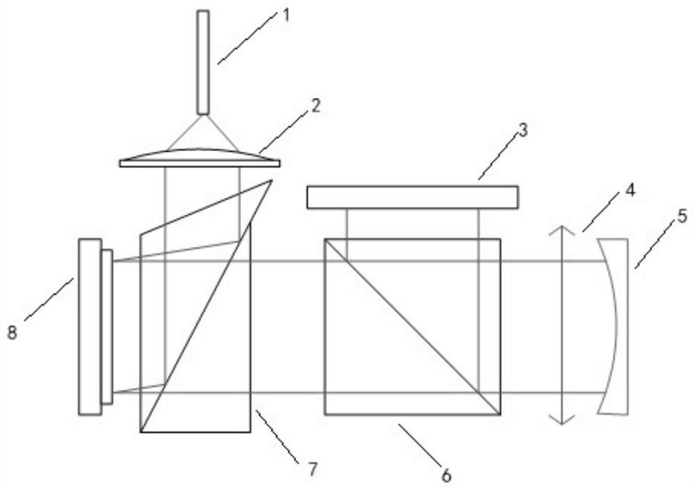
[0046] see figure 2 , a ray tracing three-dimensional measuring system for surface shape of the present invention measures reflective samples, including a light source, a shaping and collimating lens, a micro-mirror array DMD, a TIR prism, a beam splitting prism, a lens group, a sample to be measured, and a precise movement Mechanism detector CCD. Based on the ray tracing principle and the light field representation method, the system obtains the wavefront information and surface shape information of the reflective sample.
[0047] To build the graphic system, first place the sample to be tested on the standard reflector, use the computer to control the light source and the micro-mirror array DMD, encode the incident light with structured light, and control the detector CCD to move along the direction of the main light through a precise motion mechanism to obtain The position, angle and light intensity information of the incident light is used to complete the system calibrat...
Embodiment 3
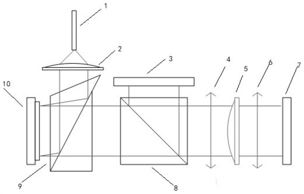
[0051] see image 3 , a ray tracing surface shape three-dimensional measurement system of the present invention measures the surface shape and position information of two surfaces of a transmission sample, including a light source, a shaping and collimating lens, a micromirror array DMD, a TIR prism, a beam splitting prism, and a lens Group, sample to be tested, lens, detector CCD1 with precision motion mechanism and detector CCD2 with precision motion mechanism. Based on the ray tracing principle and light field representation method, the system obtains the surface shape and position information of the two surfaces of the transmission sample.
[0052] To build the graphic system, first place the sample to be tested on a standard parallel plate coated with semi-transparent and semi-reflective film, use the computer to control the light source and the micro-mirror array DMD, encode the incident light with structured light, and control the detector CCD1 through a precise motion ...
PUM
 Abstract
Description
Claims
Application Information
 - R&D
- Intellectual Property
- Life Sciences
- Materials
- Tech Scout
- Unparalleled Data Quality
- Higher Quality Content
- 60% Fewer Hallucinations
Browse by: Latest US Patents, China's latest patents, Technical Efficacy Thesaurus, Application Domain, Technology Topic, Popular Technical Reports.
© 2025 PatSnap. All rights reserved.Legal|Privacy policy|Modern Slavery Act Transparency Statement|Sitemap|About US| Contact US: help@patsnap.com