
Fiber grating sensor

A fiber grating and sensor technology, applied in the field of fiber grating sensors, can solve the problems of unsatisfactory encapsulation effect of fiber grating sensors, etc.

Active Publication Date: 2018-11-06
CHINA SHENHUA ENERGY CO LTD +2
View PDF15 Cites 2 Cited by
  • Summary
  • Abstract
  • Description
  • Claims
  • Application Information

AI Technical Summary

Problems solved by technology

[0004] The purpose of the present invention is to provide a fiber grating sensor in order to overcome the unsatisfactory packaging effect of the fiber grating sensor in the prior art

Method used


Image

  • Fiber grating sensor
  • Fiber grating sensor
  • Fiber grating sensor

Examples


Embodiment Construction

[0027] The specific embodiments of the present invention will be described in detail below with reference to the accompanying drawings. It should be understood that the specific embodiments described herein are only used to illustrate and explain the present invention, and not to limit the present invention.

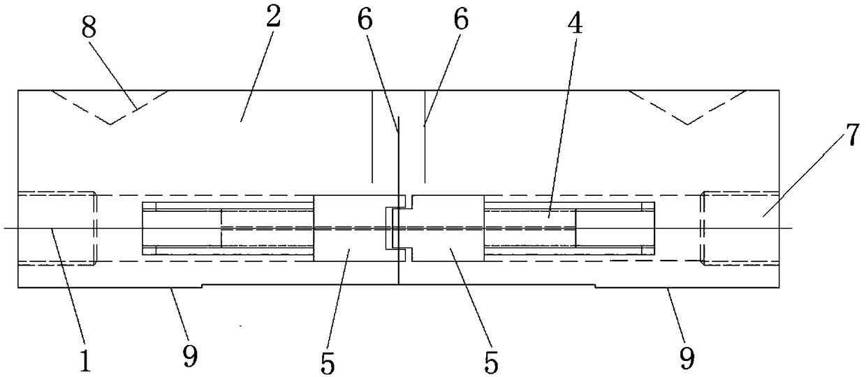
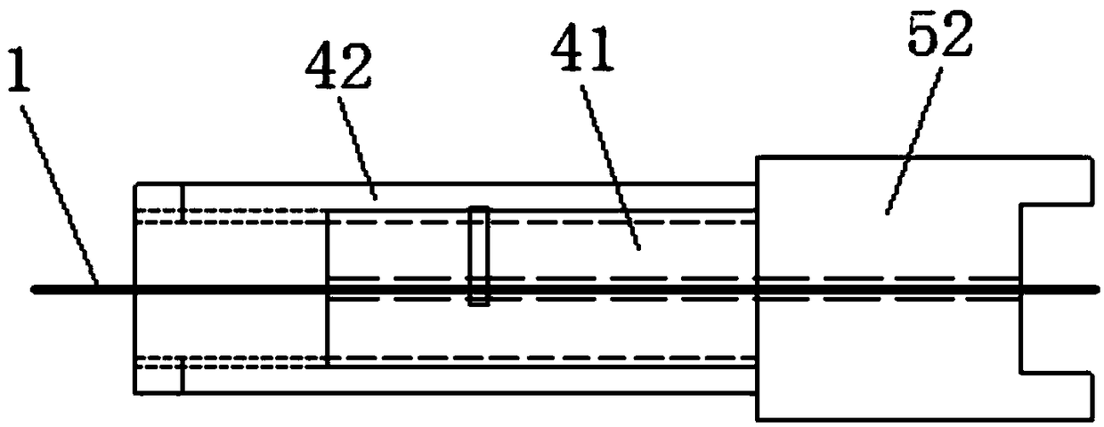
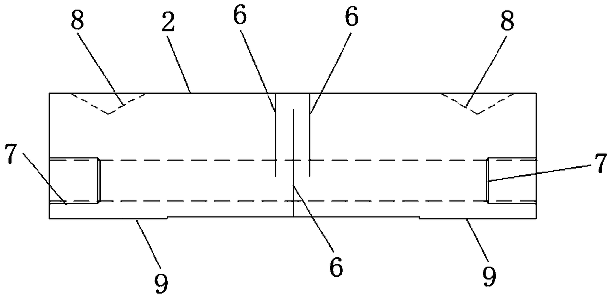
[0028] This application provides a fiber grating sensor, such as figure 1 As shown, the fiber grating sensor includes an optical fiber 1, a housing 2 and a clamping member arranged in the housing 2. The clamping member is provided with a receiving channel 3 for passing through the optical fiber 1. The clamping piece includes a pressing portion 4 for pressing the optical fiber 1 and a flange portion 5 connected to the pressing portion 4. The flange portions 5 of the two clamping pieces are arranged opposite to each other and two There is a gap between the flange portions 5 of the clamping member, the flange portion 5 is clamped in the housing 2, and the optical fiber 1 is lo...


PUM


Abstract

The invention relates to the field of application of fiber gratings, and discloses a fiber grating sensor. The fiber grating sensor comprises a fiber (1), a shell (2) and clamping pieces arranged in the shell (2), wherein the clamping piece is provided with an accommodating channel (3) for enabling the fiber (1) to pass through; the clamping piece comprises a pressing part (4) for pressing the fiber (1) and a convex edge part (5) connected with the pressing part (4); the convex edge part (5) is clamped in the shell (2); the convex edge parts (5) of the two clamping pieces are arranged oppositely and a gap is left between the convex edge parts of the two clamping pieces; and the part, located between the pressing parts (4) of the two clamping pieces, of the fiber (1) is provided with a grating. The fiber grating sensor provided in the invention is bonded with no need of a polymeric material and has good reliability and practicability.

Description

Technical field [0001] The invention relates to the application field of fiber gratings, in particular to a fiber grating sensor. Background technique [0002] Due to the excellent physical, chemical, mechanical and transmission properties of optical fibers, optical fiber sensors have the characteristics of good electrical insulation, fast response speed, large dynamic range, long transmission distance, corrosion resistance, and low cost. The center wavelength of the fiber grating can be directly modulated by strain and has a good linear response. It is an ideal strain measuring element. At present, the application of optical fiber sensors in military, scientific research, industry, commerce, medicine and other fields is becoming more and more extensive. However, the core diameter of the bare fiber grating is small, particularly fragile, has poor shear resistance, and is easily damaged and cannot be directly used in engineering. Therefore, it is particularly important to package...

Claims


Application Information

Patent Timeline
IPC IPC(8): G01B11/02G01B11/16
CPCG01B11/02G01B11/165
Inventor 丰汉羽陈保平刘振东崔培叶茂林燕延
Owner CHINA SHENHUA ENERGY CO LTD
Learn More