Water purifier booster pump, booster water supply system and booster method

A technology for water purifiers and booster pumps, applied to pumps, pump components, machines/engines, etc., can solve the problems of reduced filtration efficiency, affecting the use of water purifiers, and increased pressure loss, achieving low operating noise and driving The effect of flexible method and few parts

Active Publication Date: 2021-03-30
LONGKOU LIJIA ELECTRIC CO LTD
View PDF7 Cites 0 Cited by
  • Summary
  • Abstract
  • Description
  • Claims
  • Application Information

AI Technical Summary

Problems solved by technology

[0005] Since the coarse particle impurities in the tap water must first pass through this stage of filtration, its working condition directly affects the use effect of the water purifier. If the continuous high pressure will make its material continue to be under pressure, the fine impurities will accumulate in the same pore, and Due to the penetration of impurities, the filtration efficiency decreases rapidly and the pressure loss increases

Method used


Image

  • Water purifier booster pump, booster water supply system and booster method
  • Water purifier booster pump, booster water supply system and booster method
  • Water purifier booster pump, booster water supply system and booster method

Examples


Embodiment 1

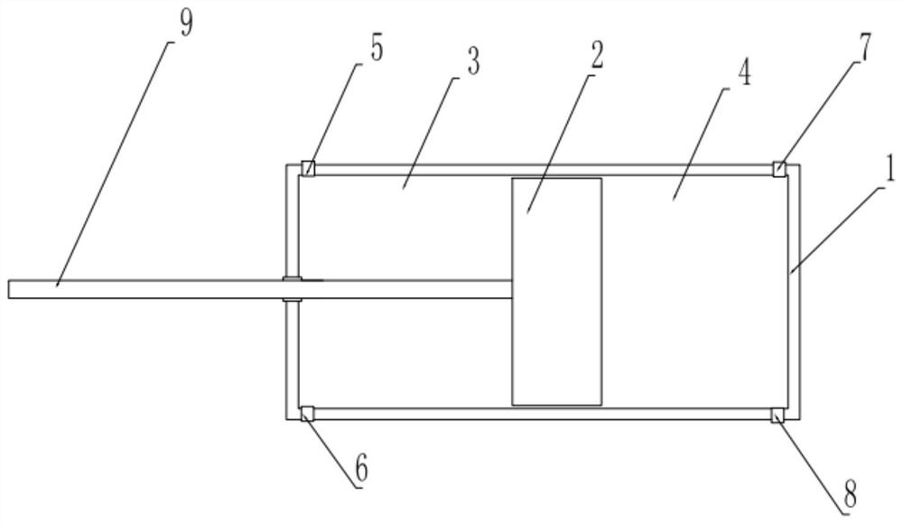
[0031] A water purifier booster pump, comprising a pump body and a drive mechanism, the pump body includes a cylindrical closed cylinder 1, a piston 2 is arranged inside the cylindrical closed cylinder 1, and the piston 2 pushes the cylinder The closed cylinder body is divided into a left pressurized tank 3 and a right pressurized tank 4, a left water inlet 5 and a left water outlet 6 are arranged at the end of the left pressurized tank 3, and the end of the right pressurized tank 4 There is a right water inlet 7 and a right water outlet 8;

[0032] The piston 2 is provided with a piston rod 9, one end of the piston rod 9 is connected to the piston 2, and the other end extends out of the cylindrical closed cylinder 1 and is connected with the drive mechanism 10;

[0033] The driving mechanism 10 can drive the piston 2 to reciprocate left and right.

[0034] The driving mechanism 10 is a linear motor, a two-way cylinder or a crank linkage mechanism.

Embodiment 2

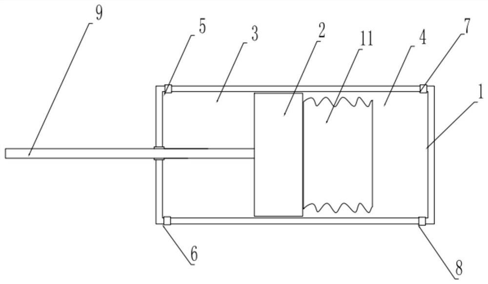
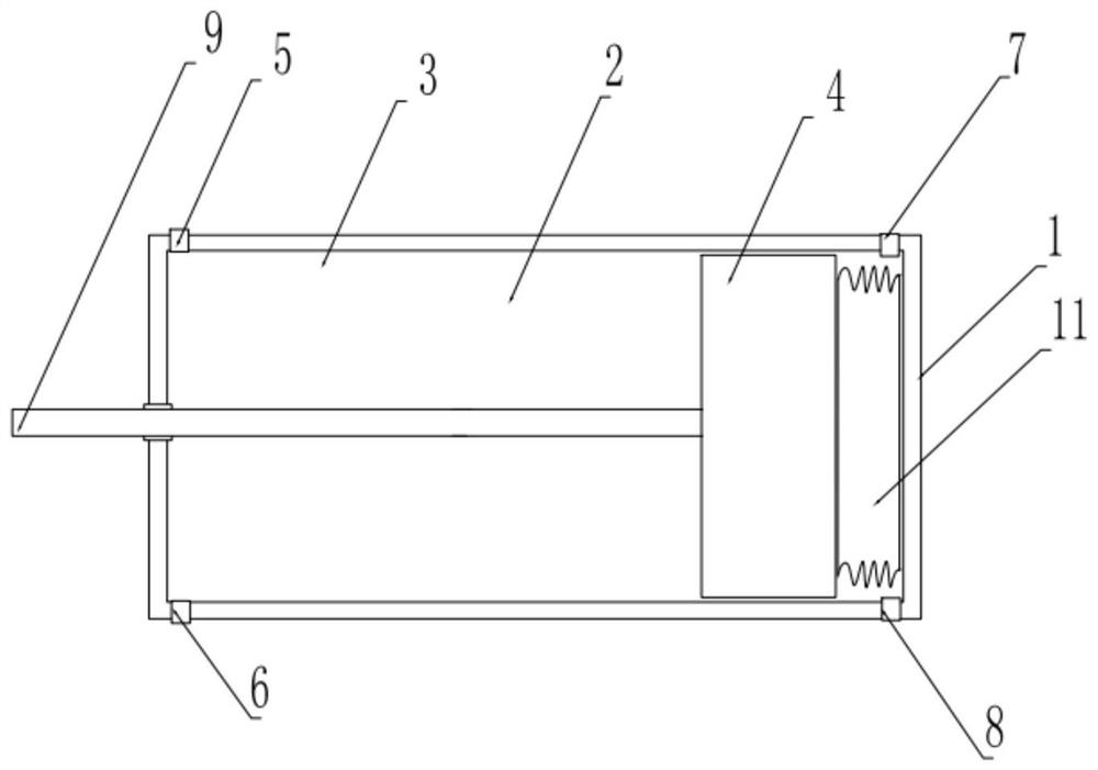
[0036] The difference from Embodiment 1 is that a compressible air bag 11 is also provided in the left pressurized chamber 3 or the right pressurized water chamber 4, and the compressed air bag 11 is fixedly connected with the piston 2. In the middle position, the length of the cavity of the pressurized water chamber provided with the compressed air bag 11 is greater than the length of the cavity of the pressurized water chamber not provided with the compressed air bag. The length difference between the two pressurized water chambers should be smaller than the length of the compressed air bag 11 in the uncompressed state, so as to ensure the alternate high and low pressure water supply.

[0037] The rest are the same as in Embodiment 1 and will not be repeated here.

[0038] The working principle of embodiment 2 is the same as that of embodiment 1. Since the compressible air bag 11 has a certain internal pressure, when the pressurized water chamber is in the state of absorbing...


PUM


Abstract

The invention relates to the technical field of water purifier pressurization, in particular to a water purifier booster pump, which includes a pump body and a driving mechanism, and is characterized in that the pump body includes a cylindrical closed cylinder, and the cylindrical closed A piston is arranged in the cylinder, and the piston divides the cylindrical closed cylinder into a left pressurized tank and a right pressurized tank, and left water inlets are respectively provided at the ends of the left pressurized tank and the right pressurized tank , the left water outlet; the right water inlet, the right water outlet; the piston is provided with a piston rod, one end of the piston rod is connected to the piston, and the other end extends out of the cylindrical closed cylinder and is connected with the drive mechanism ; Also relates to a water purifier pressurization system and a pressurization method. The beneficial effects of the present invention are firstly simple in structure and longer in life; secondly, it is convenient to adjust the reciprocating frequency to set the pressurization range; thirdly, the running noise is low; fourthly, it is especially beneficial for the first-stage filtering PP cotton filter element to better maintain the outer layer Loose state, exert better filtration performance.

Description

technical field [0001] The invention relates to the technical field of water purifier boosting, in particular to a water purifier booster pump, and also relates to a water purifier booster system and a booster method. Background technique [0002] At present, water purifiers have been widely used in households, factories, hotels and other occasions; conventional water purifiers include successively cascaded polypropylene melt spray elements, activated carbon filter elements, ultrafiltration membranes and post-installed activated carbon filter elements. This multi-stage filter element structure requires that the water supply must ensure a certain pressure to achieve the required filtering effect and flow rate; since tap water with a normal flow rate needs to be pressurized through the filter element, the booster pump is almost a must for the water inlet Configuration, the diaphragm booster pump is widely used in various brands of water purifiers because of its advantages of "...

Claims


Application Information

Patent Timeline
Patent Type & Authority Patents(China)
IPC IPC(8): F04B19/22F04B53/16F04B53/14
CPCF04B19/22F04B53/14F04B53/162
Inventor 李忠维崔兴武徐亮栾景坤戴旭丁泰文
Owner LONGKOU LIJIA ELECTRIC CO LTD
Why Eureka
Try Eureka