
Tunnel ventilating system and method

A tunnel ventilation and cross-channel technology, which is used in mine/tunnel ventilation, tunnels, and earth-moving drilling and mining, etc., can solve the problems of high power consumption, high operation and maintenance costs, and large air leakage rate of air ducts.

Pending Publication Date: 2018-11-06
NO 5 ENG OF CHINA RAILWAY 19 BUREAU GRP
View PDF0 Cites 4 Cited by
  • Summary
  • Abstract
  • Description
  • Claims
  • Application Information

AI Technical Summary

Problems solved by technology

The disadvantage of this ventilation method is that the fresh air drawn in by the axial flow fan from the entrance of the inclined shaft needs to be transported to the face of the tunnel by the air duct through a long distance, which requires more air ducts and a longer time. The air leakage rate of the air duct is relatively large, and the ventilation efficiency is difficult to guarantee
In addition, because the axial flow fan at the inclined wellhead needs to send air to the vicinity of the tunnel face at one time, when the air supply distance is too long, the fan needs to operate at high power for a long time, which consumes a lot of power, causes great damage to the fan, and high operation and maintenance costs

Method used

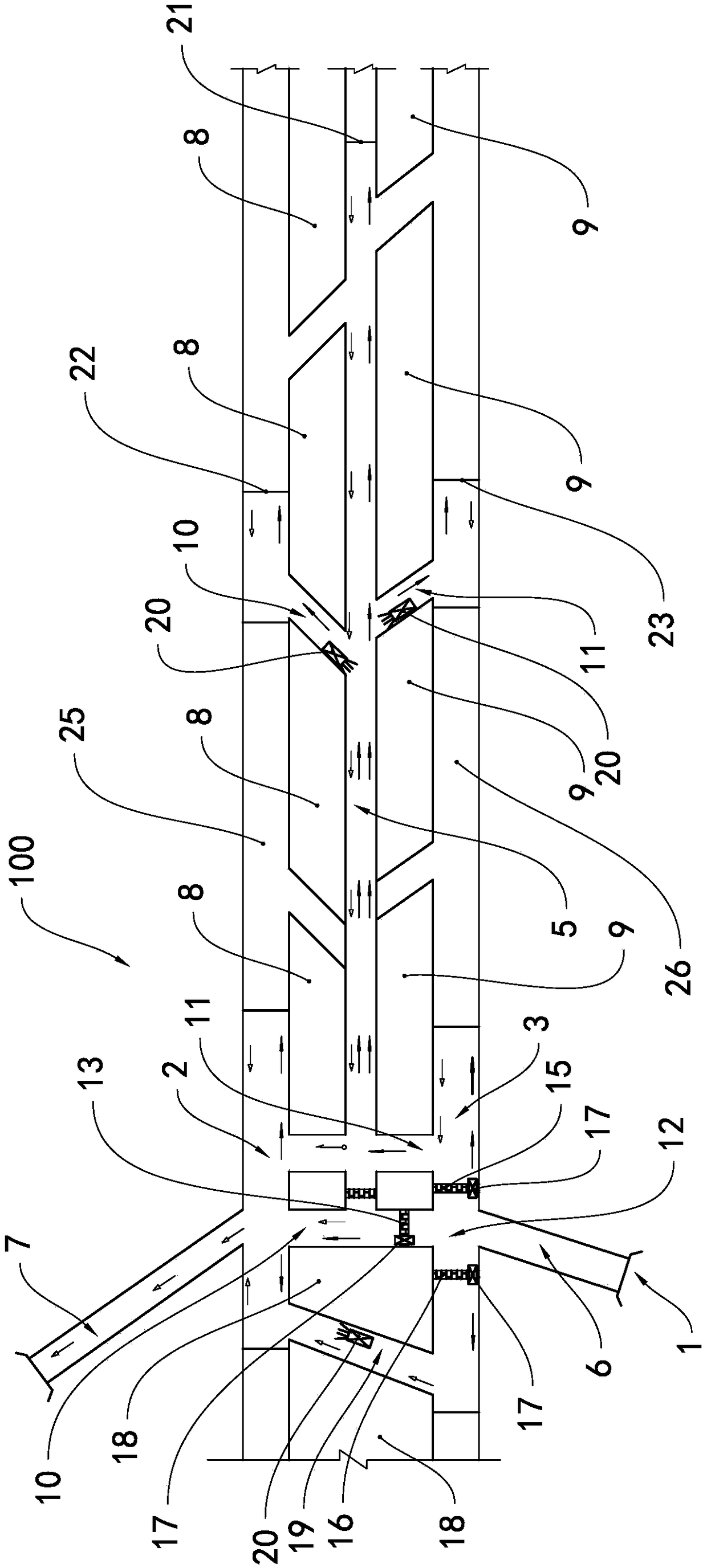

Image

  • Tunnel ventilating system and method
  • Tunnel ventilating system and method
  • Tunnel ventilating system and method

Examples


Embodiment Construction

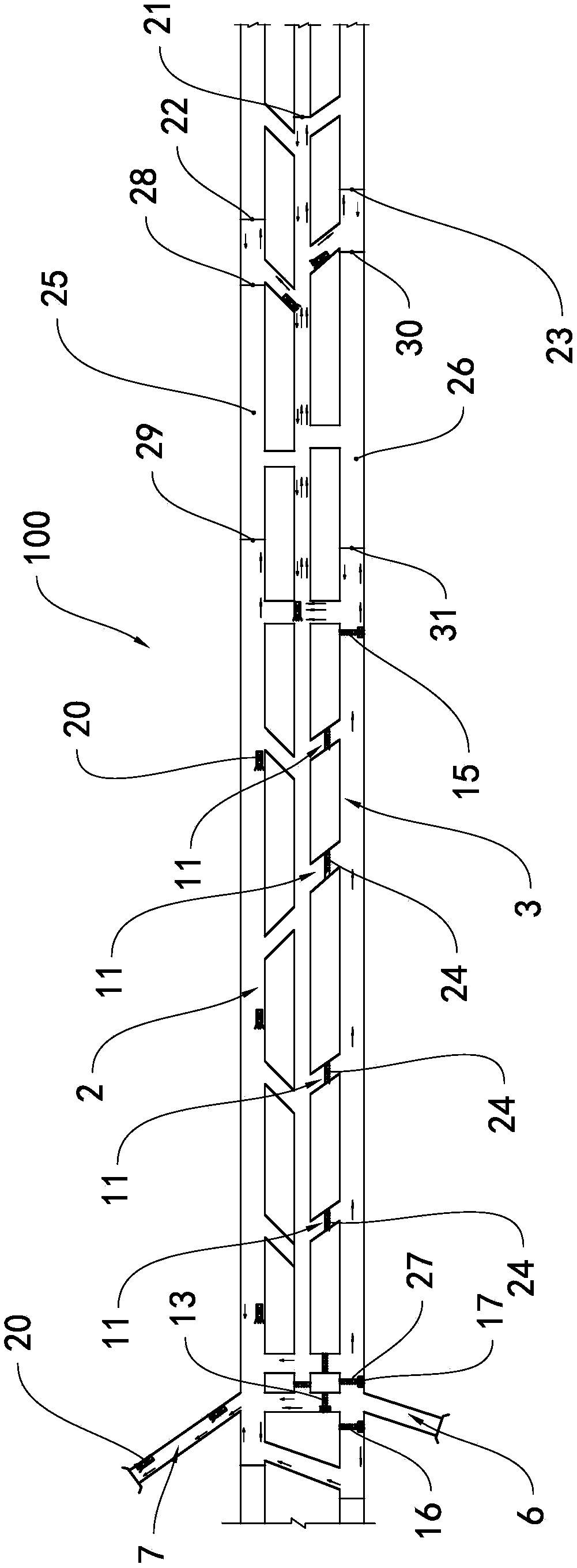
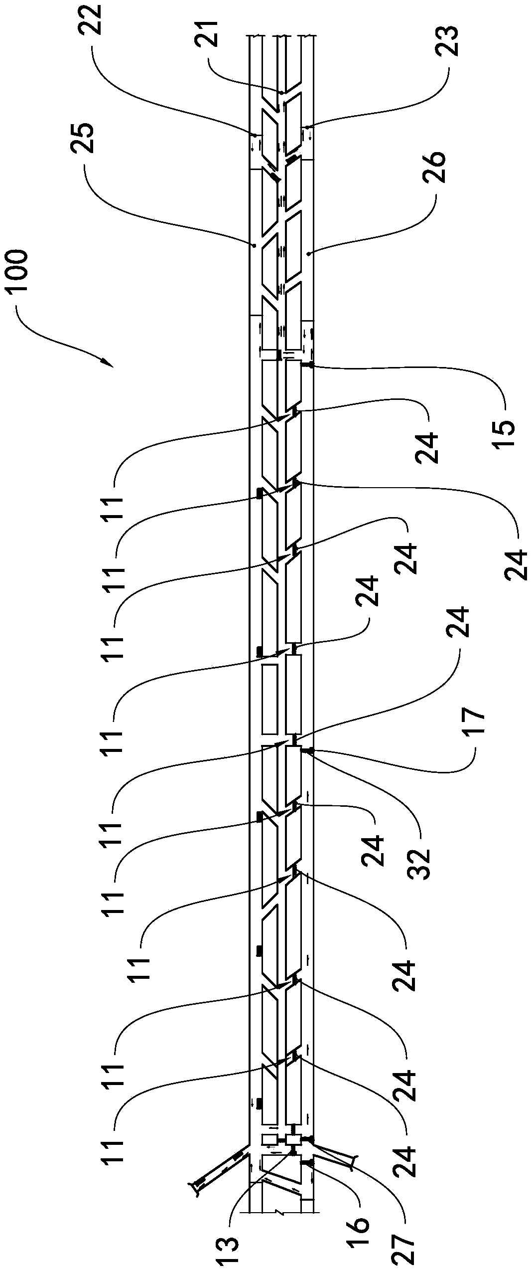
[0023] see Figure 1 to Figure 3 , the tunnel ventilation system 100 of this embodiment includes a drainage tunnel 1, a left line 2, a right line 3, a flat guide 5, a total air inlet lane 6, a total air return lane 7, a plurality of left crossways 8 and a plurality of right crossways 9 , the direction along the tunnel construction is the front direction, the total air intake lane 6 connects the right line 3 and the drainage tunnel 1, the total return air lane 7 connects the left line 2, and the left line 2 and the right line 3 are respectively arranged on the two sides of the flat guide 5. On the side, the left horizontal road 8 is located between the left line 2 and the flat guide 5, and the right horizontal road 9 is located between the right line 3 and the flat guide 5; a left road 10 is arranged between the two left cross roads 8, and the left road 10 connects the flat guide 5 and the left road. Line 2, a right passage 11 is arranged between the two right cross passages 9,...


PUM


Abstract

The invention provides a tunnel ventilating system and method. The tunnel ventilating system comprises a draining tunnel, a left line, a right line, a parallel adit, a total intake airflow roadway, atotal return airflow roadway, a plurality of left cross roads and a plurality of right cross roads. The total intake airflow roadway is connected with the right line and the draining tunnel, and the total return airflow roadway communicates with the left line. A left road communicates with the parallel adit and the left line, and a right road communicates with the parallel adit and the right line.An air chamber is formed in the communicating position of the total intake airflow roadway and the right line. The tunnel ventilating method comprises the steps that the first excavation face of theparallel adit, the left excavation face of the left line and the right excavation face of the right line are constructed, and the first excavation face of the parallel adit is constructed by a presetdistance in advance relative to the left excavation face of the left line and the right excavation face of the right line; the left road communicating with the parallel adit and the left line is formed between the two left cross roads, and the right road communicating with the parallel adit and the right line is formed between the two right cross roads; and a front air partition moves forwards toprolong the air chamber. The air chamber is prolonged forwards by stages, the pressure of one-time long-distance ventilation is relieved, and the ventilation efficiency is improved.

Description

technical field [0001] The invention relates to the technical field of tunnel construction, in particular to a tunnel ventilation system and a tunnel ventilation method for long-distance construction of extra-long tunnels. Background technique [0002] Ventilation is an indispensable technical link in the tunnel construction of railways, highways, water conservancy, hydropower, industrial and mining, national defense projects and urban subway projects in my country, and ventilation technology is usually the technical bottleneck controlling the construction of extra-long tunnels. According to the type of air duct and the installation position of the fan, tunnel construction ventilation can be divided into two types: duct ventilation and roadway ventilation. In the early days, the main fan long air duct press-in ventilation method was used more often. This method has its own shortcomings that are difficult to overcome, such as a large number of fans, high power, frequent disas...

Claims


Application Information

Patent Timeline
IPC IPC(8): E21F1/00E21F1/08E21D9/14
CPCE21D9/14E21F1/006E21F1/08
Inventor 王俊涛刘国强周宝春王海亮吴荣宝高勇陈思阳刘超
Owner NO 5 ENG OF CHINA RAILWAY 19 BUREAU GRP
Learn More