Pressure tank convenient to lift and transport
A pressure tank and hoisting technology, applied in the field of pressure tanks, can solve the problems of no anti-collision structure, small adjustment water volume, large vibration, etc., and achieve the effects of improving stability and safety, protecting the pressure tank body, and improving stability.
- Summary
- Abstract
- Description
- Claims
- Application Information
AI Technical Summary
Problems solved by technology
Method used
Image
Examples
Embodiment 1
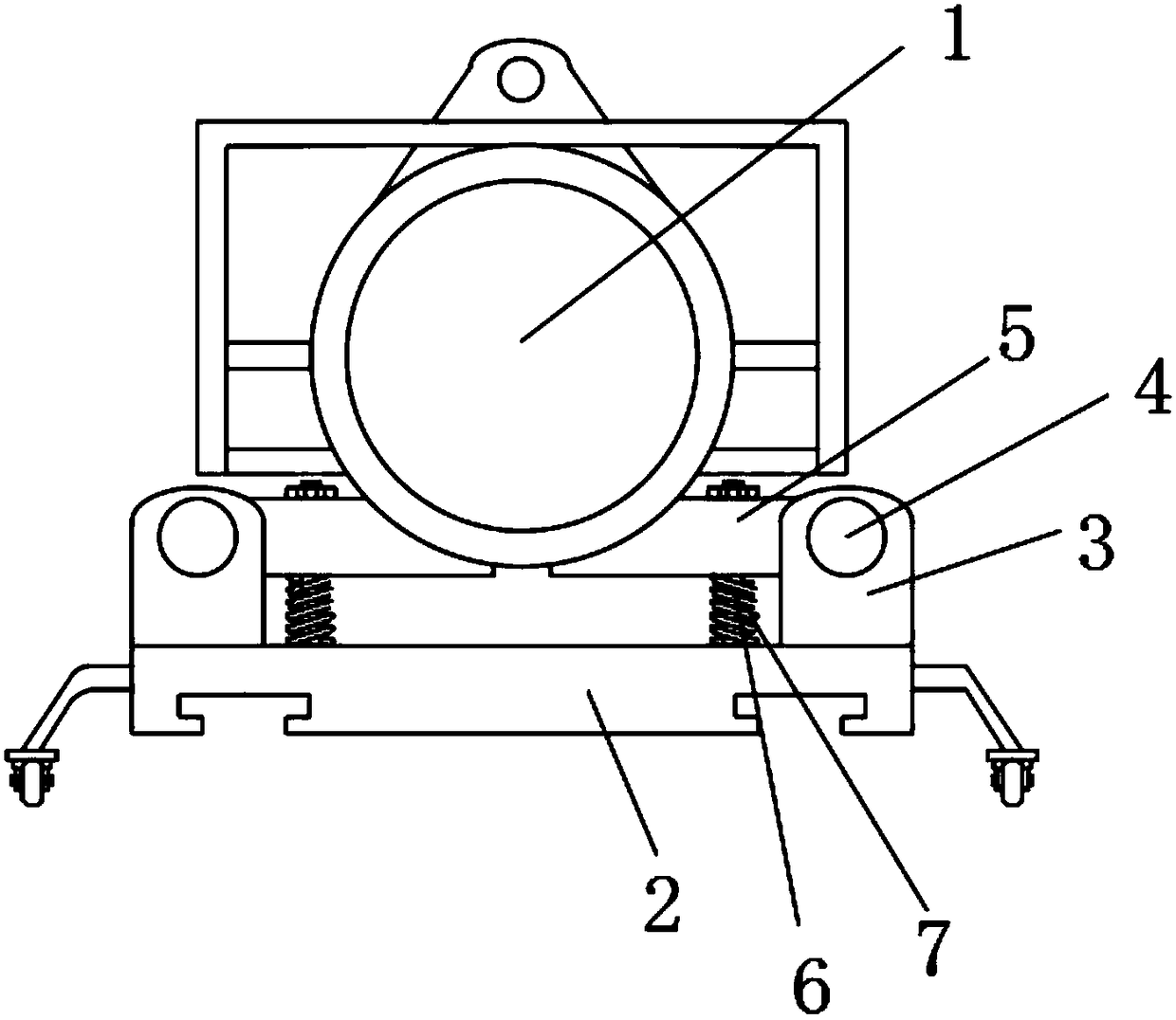
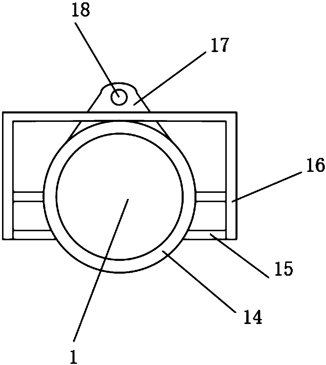
[0025] Embodiment one: refer to Figure 1-4 , a pressure tank convenient for hoisting and transportation, comprising a pressure tank body 1, a base 2 is arranged at the bottom of the pressure tank body 1, U-shaped seats 3 are welded symmetrically on both sides of the upper surface of the base 2 along the horizontal midline in the length direction, and the U-shaped seats 3. The pressure tank fixing plate 5 is connected with the rotation of the rotating shaft 4. A stop rod 6 is fixed between the pressure tank fixing plate 5 and the base 2, and the stop rod 6 is located between the pressure tank fixing plate 5 and the base 2. Shock spring 7, ring frame 14 is welded on the pressure tank body 1, U-shaped frame 16 is welded with connecting rod 15 around the outside of ring frame 14, the top of ring frame 14 is provided with lifting block 17, and the front surface of lifting block 17 is vertical There is a circular hole 18 at the position of the straight centerline, pillars 19 are sy...
Embodiment 2
[0026] Embodiment two: refer to figure 1 and Figure 4 , the pressure tank fixing plate 5 is provided with a plurality of, and a plurality of pressure tank fixing plates 5 are divided into two groups, symmetrically arranged on both sides of the pressure tank body 1, the pressure tank fixing plate 5 is used to connect the pressure tank body 1 and The base 2 is fixed in a limited position, and the fixing method is fixed by bolts.
Embodiment 3
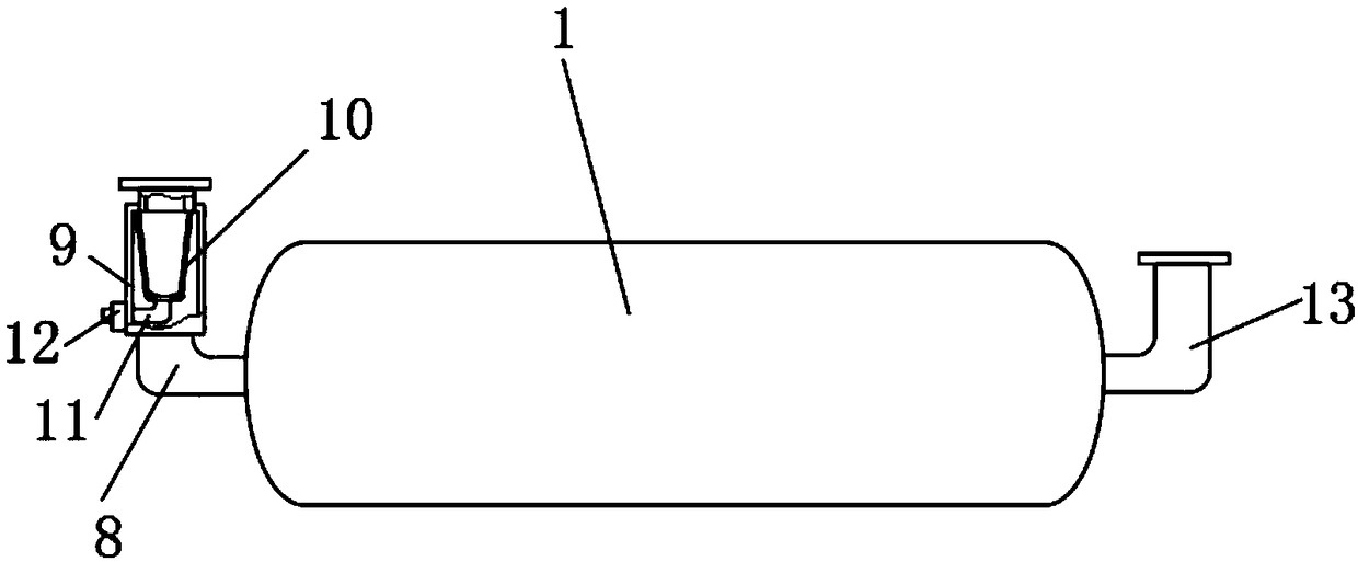
[0027] Embodiment three: refer to figure 1 and figure 2 , one end of the pressure tank body 1 is connected with a feed pipe 8, and a filter 9 is fixed on the feed pipe 8, and a filter cover 10 is clamped at the inner center of the filter 9, and the bottom end of the filter cover 10 is connected with a through filter 9 The slag discharge pipe 11, and the slag discharge pipe 11 is provided with a control valve 12, the other end of the pressure tank body 1 is connected with a discharge pipe 13, the feed pipe 8 is used for feeding the pressure tank body 1, and the filter 9 Setting, the liquid injected into the pressure tank body 1 can be filtered, and the function of the discharge pipe 13 is increased. The slag discharge pipe 11 is used to discharge the impurities generated by the filtration inside the filter cover 10, which is convenient for the cleaning of the filter 9
PUM
 Abstract
Description
Claims
Application Information
 - R&D Engineer
- R&D Manager
- IP Professional
- Industry Leading Data Capabilities
- Powerful AI technology
- Patent DNA Extraction
Browse by: Latest US Patents, China's latest patents, Technical Efficacy Thesaurus, Application Domain, Technology Topic, Popular Technical Reports.
© 2024 PatSnap. All rights reserved.Legal|Privacy policy|Modern Slavery Act Transparency Statement|Sitemap|About US| Contact US: help@patsnap.com


