Folding telescopic logistics transport vehicle
A telescopic, transporter technology, applied in the field of logistics and freight, can solve the problems of the transporter being unable to realize flipping and telescoping, insufficient operational flexibility of the transporter, and reducing the practicability of the transporter, and achieve a simple and reasonable overall structural design, easy unloading and The effect of loading processing and reducing workload
- Summary
- Abstract
- Description
- Claims
- Application Information
AI Technical Summary
Problems solved by technology
Method used
Image
Examples
Embodiment 1
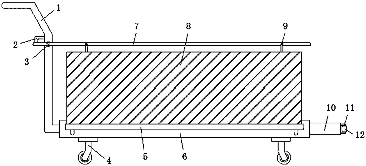
[0027] Embodiment one, with reference to Figure 1-4 , a foldable telescopic logistics transport vehicle, comprising a load plate 6, universal wheels 4 are fixed with bolts around the bottom of the load plate 6, a handle 1 is welded on the outer wall of one side of the load plate 6, and the vertical end of the handle 1 The interior is rotationally connected with the top plate 7 through the first connecting shaft 3. The outer wall of the vertical end of the handle 1 is welded with a limit rod 2 above the top plate 7. The outer walls of both sides of the load plate 6 are connected to the side walls through the second connecting shaft 5 The plate 8 is connected by rotation, the inside of the load plate 6 is provided with a groove 15, and the inner surface wall of the groove 15 is rollingly connected with a telescopic plate 10, the upper surface of the horizontal end of the side plate 8 is clamped and fixed with a hanging ring 9, and the top plate 7 The outer walls on both sides a...
Embodiment 2
[0028] Embodiment two, refer to figure 1 and Figure 4 The outer walls of both sides of the load plate 6 are welded with an anti-off rod 20 below the second drive shaft 5. The cross-sections of the anti-off rod 20 and the limit rod 2 are all L-shaped structures, and the vertical The top of the straight end is clamped and fixed with a compression spring 19. When the side plate 8 is in a horizontal state under the rotation of the second connecting shaft 5, the side plate 8 will first squeeze the compression spring 19, so that the compression spring 19 is compressed and deformed. Spring 19 is compressed to minimum value, and side plate 8 can be contacted with the vertical end top of anti-off bar 20, thereby plays the effect of cushioning shock absorption and anti-off support to side plate 8, ensures the stability of side plate 8.
Embodiment 3
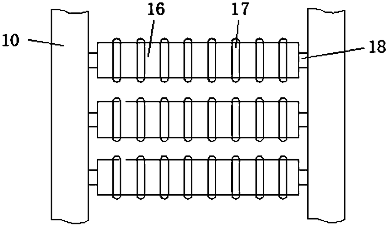
[0029] Embodiment three, refer to Figure 1-3 , the inner surface wall of the expansion plate 10 is rotationally connected with the conveying roller shaft 16 through the third connecting shaft 18, and the outer surface wall of the conveying roller shaft 16 is sleeved with a soft rubber ring 17, and the inner surface wall of the groove 15 is symmetrically rotationally connected Limited roller 14, steel rope 13 is hinged on the inner surface wall of the vertical end of groove 15, and the free end of steel rope 13 is hinged and fixed with the outer wall of expansion plate 10, when pulling expansion plate 10 outwards, expansion plate 10 It will move out from the groove 15 under the rolling of the limit roller 14. When the expansion plate 10 is pulled to the maximum value, the steel rope 13 will be straightened to play a traction role on the expansion plate 10. At this time, the transport goods can be placed On the conveying roller shaft 16, it is conveyed to the surface of the loa...
PUM
 Abstract
Description
Claims
Application Information
 - Generate Ideas
- Intellectual Property
- Life Sciences
- Materials
- Tech Scout
- Unparalleled Data Quality
- Higher Quality Content
- 60% Fewer Hallucinations
Browse by: Latest US Patents, China's latest patents, Technical Efficacy Thesaurus, Application Domain, Technology Topic, Popular Technical Reports.
© 2025 PatSnap. All rights reserved.Legal|Privacy policy|Modern Slavery Act Transparency Statement|Sitemap|About US| Contact US: help@patsnap.com


