Metal engraving machining equipment

A processing equipment and metal technology, which is applied in the field of metal engraving processing equipment, can solve the problems of limited processing range, inability to adjust the processing angle, and inability to quickly clamp workpieces to be processed, so as to achieve strong practicability, good workpiece clamping effect, and adjustable angle effect

Inactive Publication Date: 2018-11-06
TAICANG MIX MACHINERY EQUIP CO LTD
View PDF0 Cites 0 Cited by
  • Summary
  • Abstract
  • Description
  • Claims
  • Application Information

AI Technical Summary

Problems solved by technology

[0002] The metal engraving processing equipment in the prior art cannot quickly clamp the workpiece to be processed, and at the same time cannot adjust the processing angle, and the processing range is limited, so a metal engraving processing equipment is urgently needed to solve the above-mentioned problems

Method used


Image

  • Metal engraving machining equipment
  • Metal engraving machining equipment

Examples


specific Embodiment approach

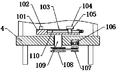
[0020] Specific implementation method: when in use, firstly, the left end face of the workpiece to be processed is closely attached to the limit block 102, and then the micro motor is operated through the control switch, and the micro motor drives the screw rod 110 to rotate in the groove 103, and the ball nut pair drives the screw rod 110. The rotary motion is converted into linear motion. The nut seat 105 drives the movable block 104 to move to the left. When the movable block 104 is closely attached to the right end surface of the workpiece to be processed, the micro drive motor 106 is stopped, and then the movable block 104 will be The workpiece to be processed is fixed on the support table 101. When the processing angle needs to be adjusted, the driving motor 106 is operated, and the driving motor 106 drives the first sprocket 107 to rotate. The first sprocket 107 drives the second sprocket 108 to rotate through the transmission chain, and the second sprocket 108 rotates. ...


PUM


Abstract

The invention provides metal engraving machining equipment which comprises a supporting table, a limiting stopping table, a groove, a movable stopping table, a nut base, a driving motor, a first chainwheel, a second chain wheel, a driving shaft and a lead screw. The supporting table is fixed to the upper end face of a driving shaft, the limiting stopping table is fixed to the left portion of theupper side face of the supporting table, the groove is formed in the right portion of the upper side face of the supporting table, the movable stopping table is fixed to the upper end face of the nutbase, the nut base is installed on the annular side face of the lead screw, the driving motor is arranged on the right portion of the lower side face of the working table, the first chain wheel is arranged on the lower end face of the driving motor, the second chain wheel is fixed to the lower end face of the driving shaft, the driving shaft is arranged at the middle portion of the working table,and the lead screw is installed at the middle portion in the groove. By means of the design, quick clamping and engraving angle adjusting functions on to-be-machined workpieces are achieved; and the metal engraving machining equipment is reasonable in structure, good in workpiece clamping effect, adjustable in machining angle and high in practicability.

Description

technical field [0001] The invention relates to metal engraving processing equipment, which belongs to the field of metal engraving equipment. Background technique [0002] The metal engraving processing equipment in the prior art cannot quickly clamp the workpiece to be processed, and at the same time cannot adjust the processing angle, and the processing range is limited, so a metal engraving processing equipment is urgently needed to solve the above-mentioned problems. Contents of the invention [0003] Aiming at the deficiencies in the prior art, the object of the present invention is to provide a metal engraving processing equipment to solve the problems raised in the above-mentioned background technology. The present invention has reasonable structure, good workpiece clamping effect, adjustable processing angle and strong practicability. [0004] In order to achieve the above object, the present invention is achieved through the following technical solutions: a metal...

Claims


Application Information

Patent Timeline
Patent Type & Authority Applications(China)
IPC IPC(8): B23D79/00B23Q3/06B23Q1/52
CPCB23D79/00B23Q1/522B23Q3/06
Inventor 陈岭徐高扬
Owner TAICANG MIX MACHINERY EQUIP CO LTD
Why Eureka
Try Eureka