
An agricultural engineering sprayer

A technology of agricultural engineering and spraying machine, applied in the field of agriculture, can solve the problems of reduced labor intensity, low work efficiency, damage to agricultural plants and staff, etc., to achieve the effects of improving stability, avoiding shaking, and avoiding damage

Active Publication Date: 2021-08-03
山东天成农业科技有限公司
View PDF8 Cites 0 Cited by
  • Summary
  • Abstract
  • Description
  • Claims
  • Application Information

AI Technical Summary

Problems solved by technology

[0002] The agricultural engineering spraying machine is a spraying machine applied to the automation of agricultural production. The spraying device can be used to spray agricultural products conveniently, thereby reducing the labor intensity of farmers. However, during the spraying process, the spraying device and the crops are attached Combined, the area of ​​the spraying range is not large, which makes the work efficiency of the sprayer low
[0003] The Chinese patent with the authorized announcement number CN201854620U discloses a multifunctional spraying machine, including an engine, a fuel tank, a gearbox and a spraying machine. The spraying machine includes a spraying pipe and a spray rod, which can be automatically retracted through a medicine box roller, etc. The purpose of the spraying pipe is to save manpower and save labor for dredging the spraying pipe, and the length and angle of the spraying rod can be adjusted to meet the requirements of different crops and different crop areas for the spray width, but the spraying machine The area of ​​the spraying range is not large, so that the work efficiency is not high, and the pesticide is easy to disperse during the spraying process, causing damage to agricultural plants and staff

Method used


Image

  • An agricultural engineering sprayer
  • An agricultural engineering sprayer
  • An agricultural engineering sprayer

Examples


Embodiment 1

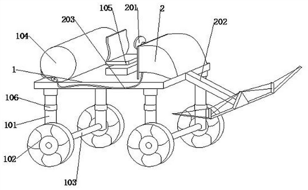
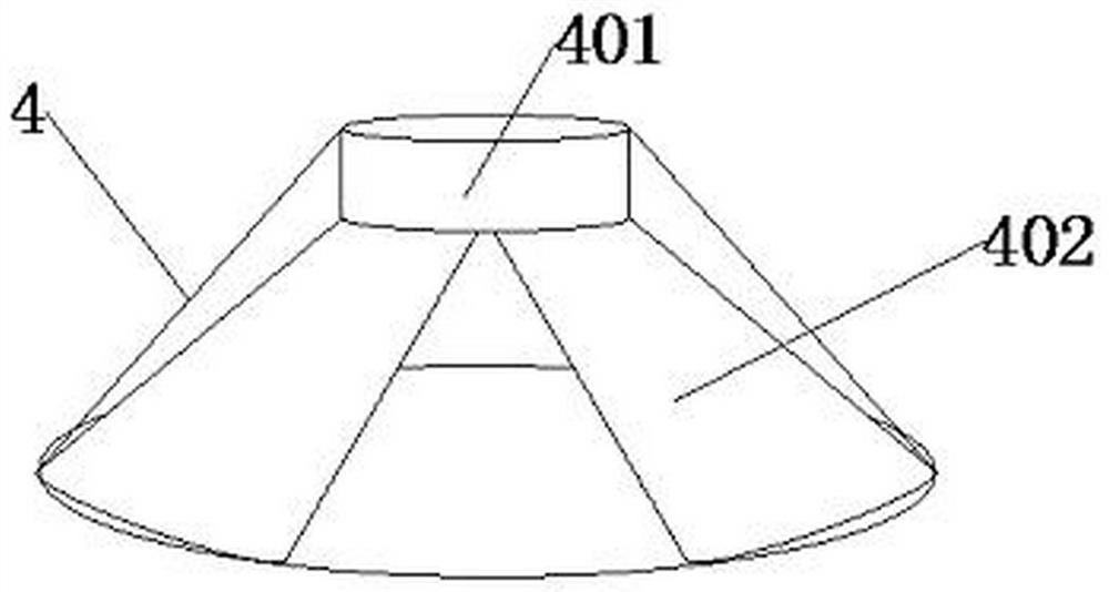
[0027] see Figure 1-4 , the present invention provides a technical solution: an agricultural engineering spraying machine, comprising a workbench 1, a spraying device 3 and a nozzle 4, a telescopic rod 202 is welded on the right side of the workbench 1, and the telescopic rod 202 is far away from the workbench 1 One side is fixedly connected with the spraying device 3, and the telescopic rod 202 is arranged obliquely to the spraying device 3, and the bottom of the spraying device 3 is fixedly connected with an arc-shaped plate 301, and the arc-shaped plate 301 is in a "U-shaped" structure, and the arc The bottom of the shaped plate 301 is movably connected with nozzles 4, and the nozzles 4 are equidistantly arranged on the bottom surface of the arc-shaped plate 301, and the outer surface of the nozzle 4 is provided with a protective shell, and the side of the arc-shaped plate 301 away from the nozzles 4 Two fixed blocks 303 are fixedly connected, and the outer surface of the ...

Embodiment 2

[0029] In the embodiment, an agricultural engineering spraying machine includes a workbench 1, a spraying device 3 and a nozzle 4, a telescopic rod 202 is welded on the right side of the workbench 1, and the side of the telescopic rod 202 away from the workbench 1 is fixedly connected There is a spraying device 3, and the telescopic rod 202 is arranged obliquely to the spraying device 3, and the bottom of the spraying device 3 is fixedly connected with an arc-shaped plate 301, and the arc-shaped plate 301 has a "U-shaped" structure, and the arc-shaped plate 301 The bottom is movably connected with nozzles 4, and the nozzles 4 are equidistantly arranged on the bottom surface of the arc-shaped plate 301, and the side of the arc-shaped plate 301 away from the nozzle 4 is fixedly connected with two fixed blocks 303, and the outer sides of the fixed blocks 303 A clasp is provided on the surface, and two drug-resistance pipes 402 are fixedly connected inside the nozzle 4, and the two...

Embodiment 3

[0032] In the embodiment, an agricultural engineering spraying machine includes a workbench 1, a spraying device 3 and a nozzle 4, a telescopic rod 202 is welded on the right side of the workbench 1, and the side of the telescopic rod 202 away from the workbench 1 is fixedly connected There is a spraying device 3, and the telescopic rod 202 is arranged obliquely to the spraying device 3, and the bottom of the spraying device 3 is fixedly connected with an arc-shaped plate 301, and the arc-shaped plate 301 has a "U-shaped" structure, and the arc-shaped plate 301 The bottom is movably connected with nozzles 4, and the nozzles 4 are equidistantly arranged on the bottom surface of the arc-shaped plate 301, and the side of the arc-shaped plate 301 away from the nozzle 4 is fixedly connected with two fixed blocks 303, and the outer sides of the fixed blocks 303 A clasp is provided on the surface, and two drug-resistance pipes 402 are fixedly connected inside the nozzle 4, and the two...


PUM


Abstract

The invention discloses an agricultural engineering pesticide spraying machine, which belongs to the field of agriculture. The key points of the technical scheme are that it includes a workbench, a pesticide spraying device and a nozzle. A telescopic rod is welded on the right side of the workbench, and the telescopic rod is far away from the side of the workbench. The spraying device is fixedly connected, and the telescopic rod is arranged obliquely to the spraying device. The bottom of the spraying device is fixedly connected with an arc-shaped plate, and the bottom of the arc-shaped plate is movably connected with nozzles, and the nozzles are evenly spaced on the arc. The bottom surface of the arc-shaped plate is fixedly connected with two fixed blocks on the side away from the nozzle, and the outer surface of the fixed block is provided with a snap ring. This kind of agricultural engineering spraying machine is fixedly installed with an arc-shaped plate under the spraying device, and nozzles are evenly distributed on the lower surface of the arc-shaped plate. The arc-shaped plate has a "U-shaped" structure, which can increase the spraying area of ​​the nozzle. , so as to avoid increasing the number of spraying, and solve the problem of low working efficiency of the spraying machine.

Description

technical field [0001] The invention relates to the field of agriculture, in particular to an agricultural engineering pesticide sprayer. Background technique [0002] The agricultural engineering spraying machine is a spraying machine applied to the automation of agricultural production. The spraying device can be used to spray agricultural products conveniently, thereby reducing the labor intensity of farmers. However, during the spraying process, the spraying device and the crops are attached Combined, the area of ​​the spraying range is not large, which makes the sprayer work less efficient. [0003] The Chinese patent with the authorized announcement number CN201854620U discloses a multi-functional spraying machine, including an engine, a fuel tank, a gearbox and a spraying machine. The spraying machine includes a spraying pipe and a spray rod, which can be automatically retracted through a medicine box roller, etc. The purpose of the spraying pipe is to save manpower ...

Claims


Application Information

Patent Timeline
Patent Type & Authority Patents(China)
IPC IPC(8): A01M7/00
CPCA01M7/0032A01M7/0082
Inventor 徐友琴
Owner 山东天成农业科技有限公司
Learn More