A connection structure and method for a concrete frame and a light steel roof

A technology for connecting structures and concrete, applied in the direction of roofs, building components, building structures, etc., can solve the problems of fighting between new foundations and existing foundations, large space for foundation optimization, and difficulty in quality control, so as to reduce damage and reduce damage. Transformation, shortening construction period and quality control, and promoting the effect of great value

Active Publication Date: 2019-10-22
XIAN CHANGQING TECH ENG
View PDF7 Cites 0 Cited by
  • Summary
  • Abstract
  • Description
  • Claims
  • Application Information

AI Technical Summary

Problems solved by technology

[0005] The purpose of the present invention is to overcome above-mentioned deficiencies in the prior art, provide a kind of concrete frame and light steel roof connection structure and method, overcome the design method construction of two frames in the prior art 1, in the extension project, joint is set The process is complicated, and it is easy to cause the new foundation at the lower part to fight with the existing foundation, which is inconvenient for construction; 2. If the structural joints are not handled properly in the later maintenance process, it is easy to cause roof water seepage and structural cracking, and this method has a long construction period and a low degree of industrialization. Quality control is difficult, and it is easy to cause a decline in project quality; 3. For new projects, two-frame frames are used at the joints, and the foundation is a double-column foundation under the column. Due to the small force of the light steel roof side frame, the foundation can be optimized. ;For the frame beam at the connection, the light steel roof requires the frame beam to be sloped at the connection (the slope is consistent with the light steel roof), but the beam doubles as the floor frame beam and cannot be sloped, etc.

Method used


Image

  • A connection structure and method for a concrete frame and a light steel roof
  • A connection structure and method for a concrete frame and a light steel roof

Examples


specific Embodiment approach

[0030] It should be noted that the structures, proportions, sizes, etc. shown in the drawings attached to this specification are only used to match the content disclosed in the specification, for those who are familiar with this technology to understand and read, and are not used to limit the implementation of the present invention Any modification of the structure, change of the proportional relationship or adjustment of the size shall still fall within the scope of the technical content disclosed in the present invention without affecting the effect and purpose of the present invention. In the range.

[0031] At the same time, terms such as "upper", "lower", "left", "right", "middle" and "one" quoted in this specification are only for the convenience of description and are not used to limit this specification. The practicable scope of the invention and the change or adjustment of its relative relationship shall also be regarded as the practicable scope of the present inventi...

Embodiment 1

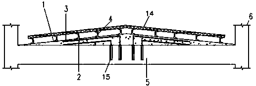
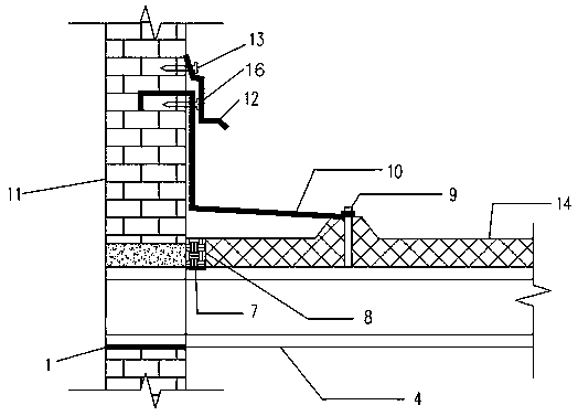
[0033] Such as Figure 1~2 As shown, the present invention discloses a connection structure between a concrete frame and a light steel roof, including a purlin supporting plate 1, a rear anchoring steel bar 2, a concrete slope layer 3, purlins 4, a concrete frame, a frame filling wall 11 and a light steel roof pressing Shaped steel plate 14, the concrete frame includes a concrete frame beam 5 and a concrete frame column 6, wherein there are two concrete frame columns 6, which are respectively arranged on both sides of the concrete frame beam 5 to support the concrete frame beam 5, and the rear anchoring steel bar 2 is A plurality of them, wherein a plurality of rear anchoring steel bars 2 are fixed on the concrete frame beam 5 to form a roof structure, wherein the concrete slope layer 3 is formed by pouring the roof structure of the rear anchoring steel bars 2, and the purlin supporting plate 1 is fixed on the concrete slope On the layer 3, the purlin 4 is fixed on the purlin ...

Embodiment 2

[0035] Such as Figure 1~2 As shown, the present invention discloses a connection structure between a concrete frame and a light steel roof, including a purlin supporting plate 1, a rear anchoring steel bar 2, a concrete slope layer 3, purlins 4, a concrete frame, a frame filling wall 11 and a light steel roof pressing Shaped steel plate 14, the concrete frame includes a concrete frame beam 5 and a concrete frame column 6, wherein there are two concrete frame columns 6, which are respectively arranged on both sides of the concrete frame beam 5 to support the concrete frame beam 5, and the rear anchoring steel bar 2 is A plurality of them, wherein a plurality of rear anchoring steel bars 2 are fixed on the concrete frame beam 5 to form a roof structure, wherein the concrete slope layer 3 is formed by pouring the roof structure of the rear anchoring steel bars 2, and the purlin supporting plate 1 is fixed on the concrete slope On the layer 3, the purlin 4 is fixed on the purlin ...


PUM


Abstract

The invention discloses a concrete frame and light steel roof connecting structure and method. The connecting structure comprises a purline support plate, rear anchor bars, a concrete sloping layer, purlines, a concrete frame, a frame fill wall and a light steel roofing profiled steel plate. The concrete frame comprises a concrete frame beam and two concrete frame columns respectively arranged ontwo sides of the concrete frame beam to support the concrete frame beam. The plurality of rear anchor bars are fixed on the concrete frame beam to form a roof structure, wherein the concrete sloping layer is formed by pouring concrete in the roof structure of the rear anchor bars, the purline support plate is fixed on the concrete sloping layer, the purlines are fixed on the purline support plate,the light steel roofing profiled steel plate is built at the upper ends of the purlines, and one end of each purline extends to be fixed inside the frame fill wall.

Description

technical field [0001] The invention belongs to the technical field of industrial and civil building structures, in particular to a connection structure and method for a concrete frame and a light steel roof. Background technique [0002] With the continuous development of industrial technology and the changes and improvements in the functional requirements of industrial buildings, the number of single-building renovation and expansion projects is increasing year by year. A large number of existing building structure facilities need to be expanded and reconstructed reasonably to achieve new functions. Addressing the relationship between the rebuilt and expanded structure and the original structure is the focus and difficulty of the design to meet new demands. [0003] When the frame flat house (floor) is connected with the sloped light steel structure roof, or when the new structure is connected with the original structure, the current common practice is to set up structural...

Claims


Application Information

Patent Timeline
Patent Type & Authority Patents(China)
IPC IPC(8): E04B7/04
Inventor 李喆郭亮刘小平徐俊民朱利捷杨宏丽郑娅娜杨丽周晓亮赵玉慧孙晓骥
Owner XIAN CHANGQING TECH ENG
Why Eureka
Try Eureka