
Passenger airbag chute channel with radial rib pattern

A radial rib, airbag technology, used in pedestrian/occupant safety arrangements, vehicle components, vehicle safety arrangements, etc.

Active Publication Date: 2021-07-13
FORD GLOBAL TECH LLC
View PDF0 Cites 0 Cited by
  • Summary
  • Abstract
  • Description
  • Claims
  • Application Information

AI Technical Summary

Problems solved by technology

Pushing up into the chute channel to evenly open the tear seam at the fascia skin is challenging as airbag deployment occurs in milliseconds

Method used


Image

  • Passenger airbag chute channel with radial rib pattern
  • Passenger airbag chute channel with radial rib pattern
  • Passenger airbag chute channel with radial rib pattern

Examples


Embodiment Construction

[0030] The disclosed air bag assembly will be better understood from the following detailed description when read in conjunction with the accompanying drawings. The detailed description and drawings provide only examples of the various inventions described herein. Those skilled in the art will appreciate that changes, modifications and alterations to the disclosed examples may be made without departing from the scope of the invention described herein. Many variations are contemplated for different applications and design considerations; however, in the interest of brevity, each contemplated variation is not described individually in the following detailed description.

[0031] In the detailed description that follows, examples of various air bag assemblies are provided. Relevant properties in the examples may be the same, similar, or dissimilar in different examples. For brevity, related features will not be described in detail. Instead, the use of a related property name w...


PUM


Abstract

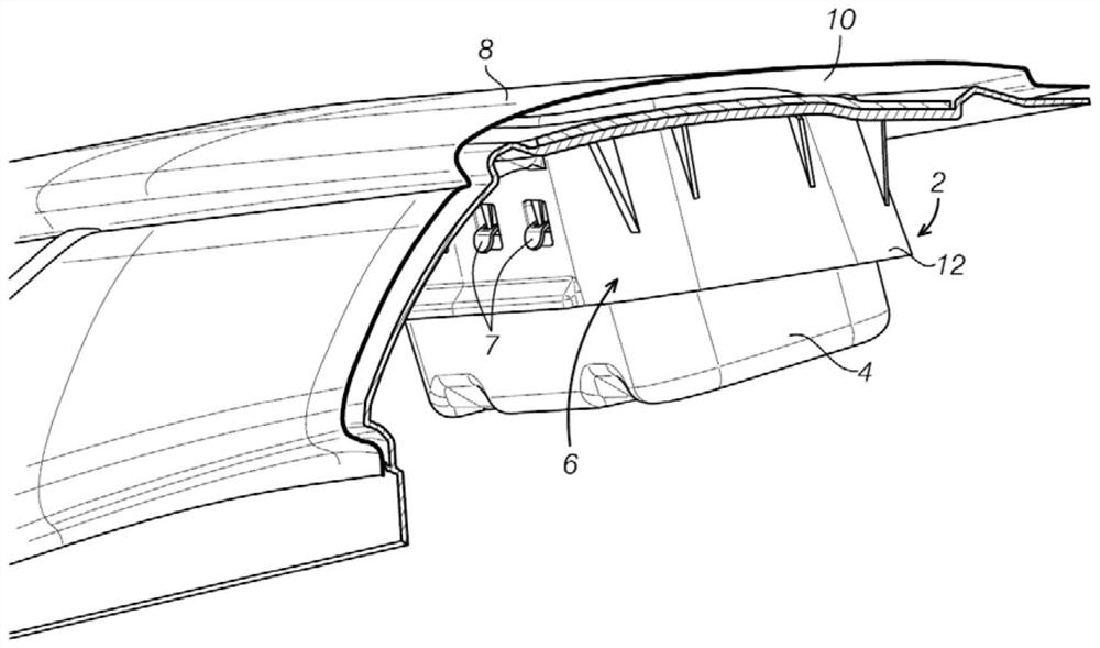
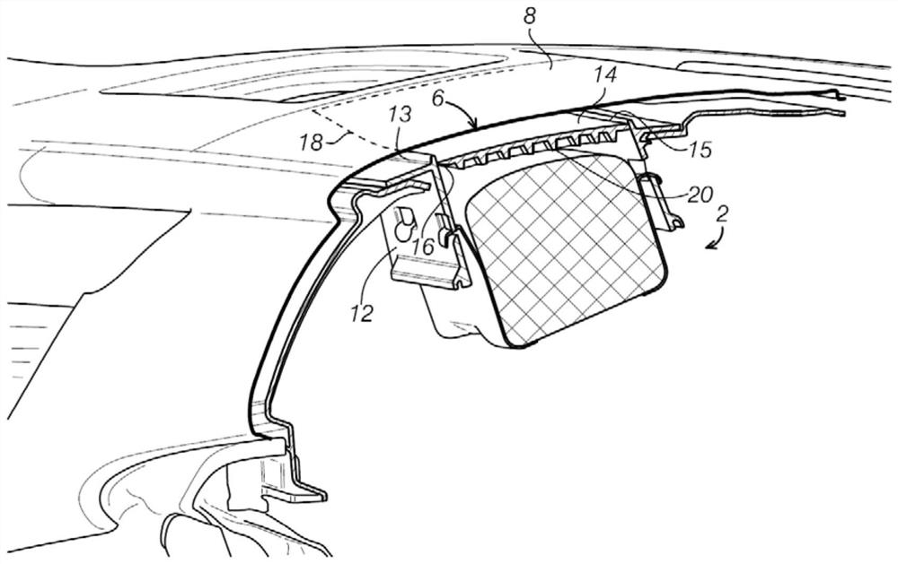
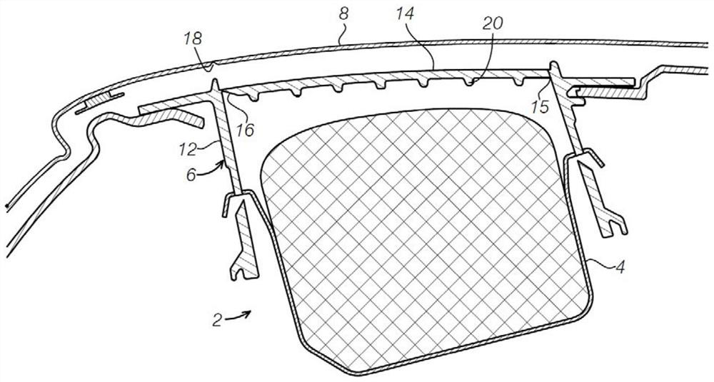
An airbag assembly is provided that includes a chute channel disposed between an instrument panel skin and an airbag module. The chute channel includes a base having a first section, and a plurality of radial ribs disposed on a surface of the base, the plurality of radial ribs extending from the middle portion to an edge of the base and configured to absorb force from airbag deployment Pass towards the tear seam in the skin of the dashboard.

Description

technical field [0001] The present disclosure relates generally to air bag assemblies in vehicles, and more particularly to air bag assemblies including passenger air bag chute channels having a radial rib pattern. Background technique [0002] The use of passenger air bags in vehicles is very common. In some vehicle designs, a passenger airbag may be attached to the transverse vehicle beam and interface with the fascia skin through the airbag chute channel. There are two weakened profiles or tear seams in the airbag assembly to allow the airbag to deploy, one at the airbag chute channel and one at the fascia skin. During a deployment event, the airbag jostles at the chute door, tearing it open, allowing the airbag to fully deploy to protect the occupants. Because airbag deployment occurs in milliseconds, pushing up into the chute channel to evenly open the tear seam at the fascia skin is challenging. The inventors have recognized that there is a need for an air bag chute...

Claims


Application Information

Patent Timeline
Patent Type & Authority Patents(China)
IPC IPC(8): B60R21/205B60R21/2165
CPCB60R21/205B60R21/2165B60R21/2176B60R21/2342
Inventor 裘德·D·苏扎武天阿丘塔·安妮迪
Owner FORD GLOBAL TECH LLC
Learn More