Vehicle rear traction connection device

A connecting device and vehicle tail technology, which is applied in traction connectors, vehicle components, transportation and packaging, etc., can solve the problems that the ball joint device is difficult to meet the needs, the height difference is not fixed, etc., to prevent up and down swing, reduce Height difference, outstanding traction effect

Active Publication Date: 2018-11-02
RONGCHENG LONGHE VEHICLE
View PDF7 Cites 1 Cited by
  • Summary
  • Abstract
  • Description
  • Claims
  • Application Information

AI Technical Summary

Problems solved by technology

In order to ensure the normal use of the ball head connector, it is required that the ball head always maintain a vertical upward posture after connection. However, the models and specifications of the towing vehicle and the towed vehicle are different, and the height difference between them is not fixed. , when the height difference between the towing vehicle and the towed vehicle changes, it is difficult to meet the needs of the fixed-structure ball joint connection device, so it is necessary to provide a connection device that can adapt to the different height differences between the towing vehicle and the towed vehicle

Method used


Image

  • Vehicle rear traction connection device
  • Vehicle rear traction connection device

Examples


Embodiment 1

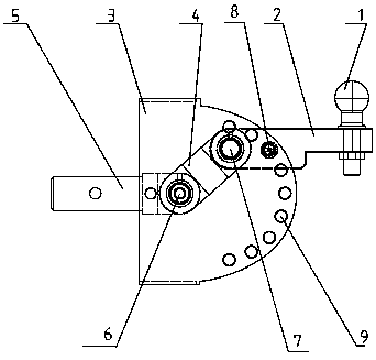
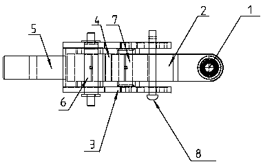
[0016] as attached figure 1 and attached figure 2 As shown, a rear traction connection device includes a connection ball 1, which is fixed at the tail end of a balance arm 2, and is connected to a ball joint of a towed vehicle during use.

[0017] as attached figure 1 and attached figure 2 As shown, it also includes the left and right wall panels 3, the rotating rod 4, the fixed rod 5, and the front end of the fixed rod 5 is used for connecting and fixing with the traction vehicle. A clamping groove is formed between the left and right wall plates 3, and the tail end of the fixed rod 5 extends into the clamping groove from the front of the clamping groove and is fixed with the left and right wall plates. The tail end is hinged.

[0018] In this embodiment, the tail end of the fixed rod 5 is provided with a U-shaped groove, one end of the rotating rod 4 is located in the U-shaped groove, and the shaft 6 passes through the left and right wall plates 3, the walls of the U-s...


PUM


Abstract

The invention relates to a traction device, and provides a vehicle rear traction connection device in order to solve the technical problem of existing connection devices during use. The vehicle rear traction connection device comprises a connection ball, and the connection ball is fixed to the front end of a balance arm; the device is characterized by further comprising left and right wall plates,a rotating rod and a fixed rod; a clamping groove is formed between the left and right wall plates, the rotating rod is located in the clamping groove, one end of the fixed rod stretches into the clamping groove and is fixedly connected with the left and right wall plates, and a first hinge shaft penetrates through the tail end of the rotating rod; the tail end of the balance arm is located in the clamping groove, a pin shaft penetrates through the portion, in the clamping groove, of an arm body of the balance arm, and the balance arm can rotate freely around the pin shaft; a second hinge shaft penetrates through the tail end of the balance arm and a rod body of the front end of the rotating rod, arc sliding grooves are formed in the left and right wall plates respectively, and the two ends of the second hinge shaft are located in the arc sliding grooves of the left and right wall plates respectively. The connection device is reasonable in structure, has an obvious shock absorption effect, and can be widely applied to connection in traction operation.

Description

technical field [0001] The invention relates to a traction device, in particular to a device for being fixed at the rear of a vehicle and connected with a traction type caravan. Background technique [0002] The trailer connection device with a ball joint is the most common, especially when ordinary vehicles are used to tow the RV, the ball joint connection device is widely used because of its small size, easy installation, and free swing. In order to ensure the normal use of the ball head connector, it is required that the ball head always maintain a vertical upward posture after connection. However, the models and specifications of the towing vehicle and the towed vehicle are different, and the height difference between them is not fixed. , when the height difference between the towing vehicle and the towed vehicle changes, it is difficult to meet the needs of the fixed structure of the ball joint connection device, so it is necessary to provide a connection device that ca...

Claims


Application Information

Patent Timeline
Patent Type & Authority Applications(China)
IPC IPC(8): B60D1/42
CPCB60D1/42
Inventor 王历涛
Owner RONGCHENG LONGHE VEHICLE
Why Eureka
Try Eureka