Installation and debugging combined tool applied to compressor instrument probe

A technology of installation, debugging, and combination of tools, applied in the direction of manufacturing tools, instruments, measuring devices, etc., can solve the problems of difficulty in guaranteeing, the gap between the instrument probe and the surface of the compressor shaft does not change, and achieve the effect of convenient use.

Pending Publication Date: 2018-11-02
ANHUI LIUGUO CHEM CO LTD
View PDF5 Cites 0 Cited by
  • Summary
  • Abstract
  • Description
  • Claims
  • Application Information

AI Technical Summary

Problems solved by technology

However, in the actual installation and debugging process, it is very difficult to ensure that the g...

Method used


Image

  • Installation and debugging combined tool applied to compressor instrument probe
  • Installation and debugging combined tool applied to compressor instrument probe
  • Installation and debugging combined tool applied to compressor instrument probe

Examples


Embodiment Construction

[0025] Below in conjunction with embodiment technical solution of the present invention is made more specific description:

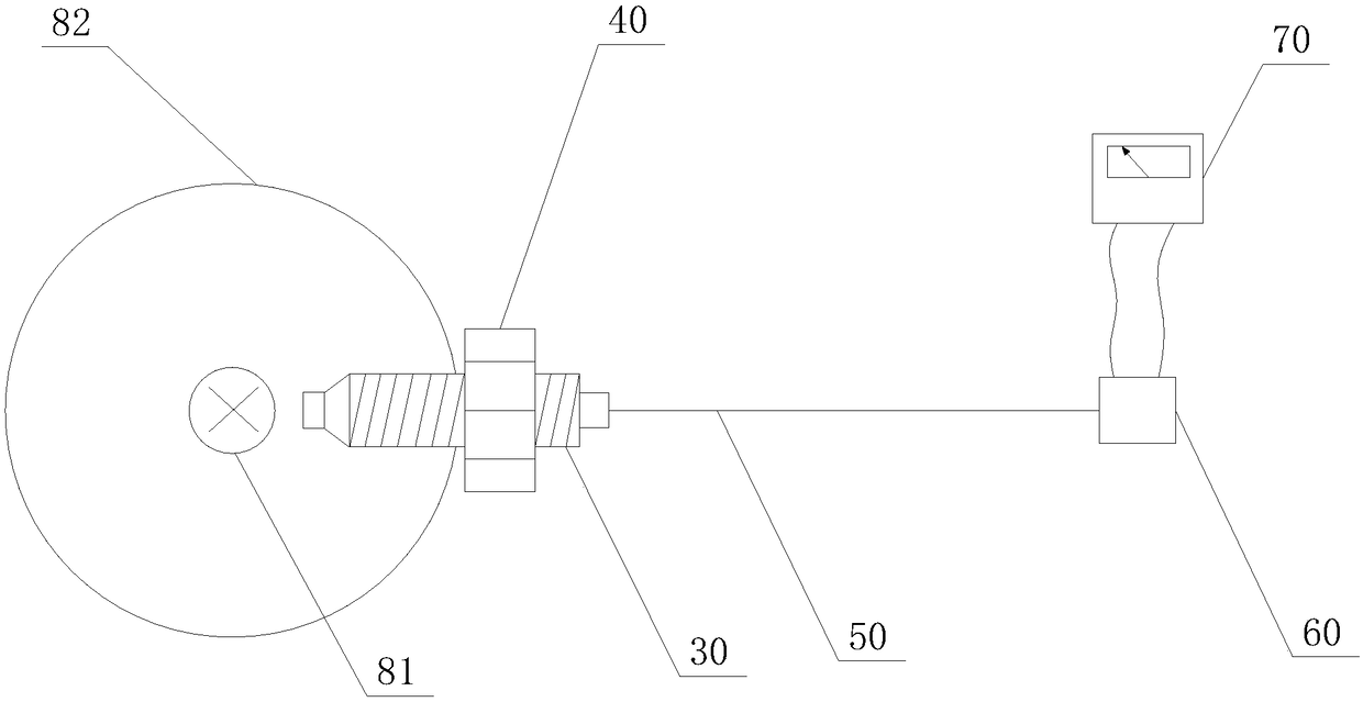
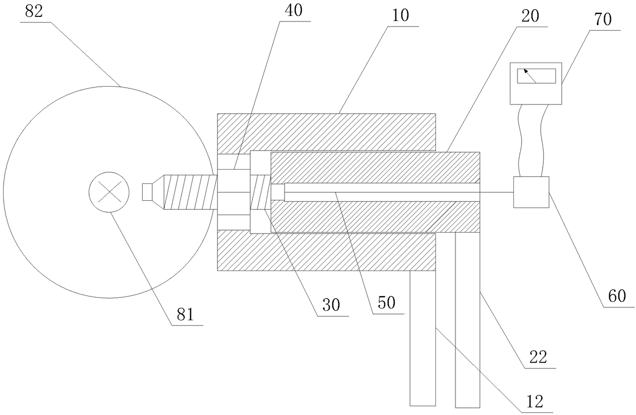
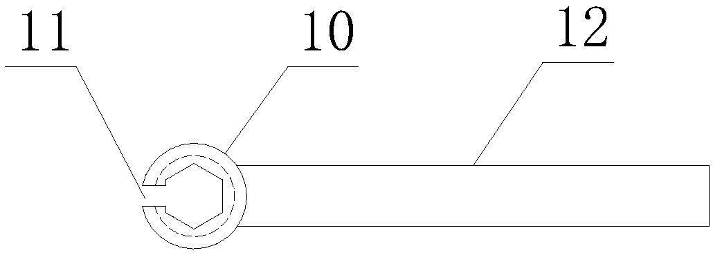
[0026] Such as figure 2 As shown: the present invention includes an outer rotation sleeve 10 and an inner rotation sleeve 20 arranged coaxially, and the outer rotation sleeve 10 is sleeved on a lock nut 40 for fixing the instrument probe 30 and is connected to the The locking nut 40 is engaged to realize the synchronous rotation of the locking nut 40 with the outer rotating sleeve 10, and the inner rotating sleeve 20 is sleeved on the instrument probe 30 and engaged with the instrument probe 30 to realize the described The instrument probe 30 rotates synchronously with the inner rotating sleeve 20 . The present invention can realize that the locking nut 40 fixes the instrument probe 30 without changing the gap between the instrument probe 30 and the side of the compressor shaft 81, so as to ensure that the instrument probe 30 meets the installation tec...


PUM


Abstract

The invention relates to an installation and debugging combined tool applied to a compressor instrument probe. The installation and debugging combined tool comprises an outer rotary sleeve and an inner rotary sleeve, which are coaxially arranged, wherein the outer rotary sleeve sleeves a locking nut for fixing the instrument probe and is clamped with the locking nut to synchronously rotate the locking nut along the outer rotary sleeve; the inner rotary sleeve sleeves the instrument probe and is clamped with the instrument probe to synchronously rotate the instrument probe along the inner rotary sleeve. According to the installation and debugging combined tool provided by the invention, the instrument probe can be fixed through the locking nut; meanwhile, a gap between the instrument probeand a side face of a compressor shaft is not changed, so that the instrument probe meets the requirements of an installation technology.

Description

technical field [0001] The invention belongs to the technical field of compressor installation, and in particular relates to a combined tool for installing and debugging instrument probes of compressors. Background technique [0002] The technical requirements for the installation of instrument probes for measuring displacement and vibration used in steam turbine compressor units are as follows: the gap between the instrument probe and the compressor shaft surface should be controlled near the middle value of the linear range, so that the upper and lower limits have sufficient margins. For example, the linear range of the gap between the instrument probe and the compressor shaft surface is 0.25-2.25mm, then the installation gap between the probe and the compressor shaft surface should be adjusted to 1.25mm, and the gap voltage is 10V (corresponding to a sensitivity of 8V / mm sensor). When installing and debugging, the instrument probe must be connected in the circuit loop, s...

Claims


Application Information

Patent Timeline
IPC IPC(8): B25B27/00G01D21/02
CPCG01D21/02B25B27/00
Inventor 蒋振李秀兰
Owner ANHUI LIUGUO CHEM CO LTD
Why Eureka
Try Eureka