Gas well leaking stoppage device and gas well drilling equipment

A gas well and drilling technology, which is applied in the field of gas well plugging devices and gas well drilling equipment, can solve the problems of difficult gas well leakage repair and repair, poor effect, etc., and achieve the elimination of the possibility of flash explosion accidents, simple structure and low cost Effect

Pending Publication Date: 2018-10-30
杨福苗
View PDF0 Cites 0 Cited by
  • Summary
  • Abstract
  • Description
  • Claims
  • Application Information

AI Technical Summary

Problems solved by technology

[0004] The purpose of the present invention is to provide a gas well plugging device and gas well drilling equipment, which aims to improve the existing problems of difficult gas well leakage repair and repair and poor effect

Method used


Image

  • Gas well leaking stoppage device and gas well drilling equipment
  • Gas well leaking stoppage device and gas well drilling equipment
  • Gas well leaking stoppage device and gas well drilling equipment

Examples


Embodiment

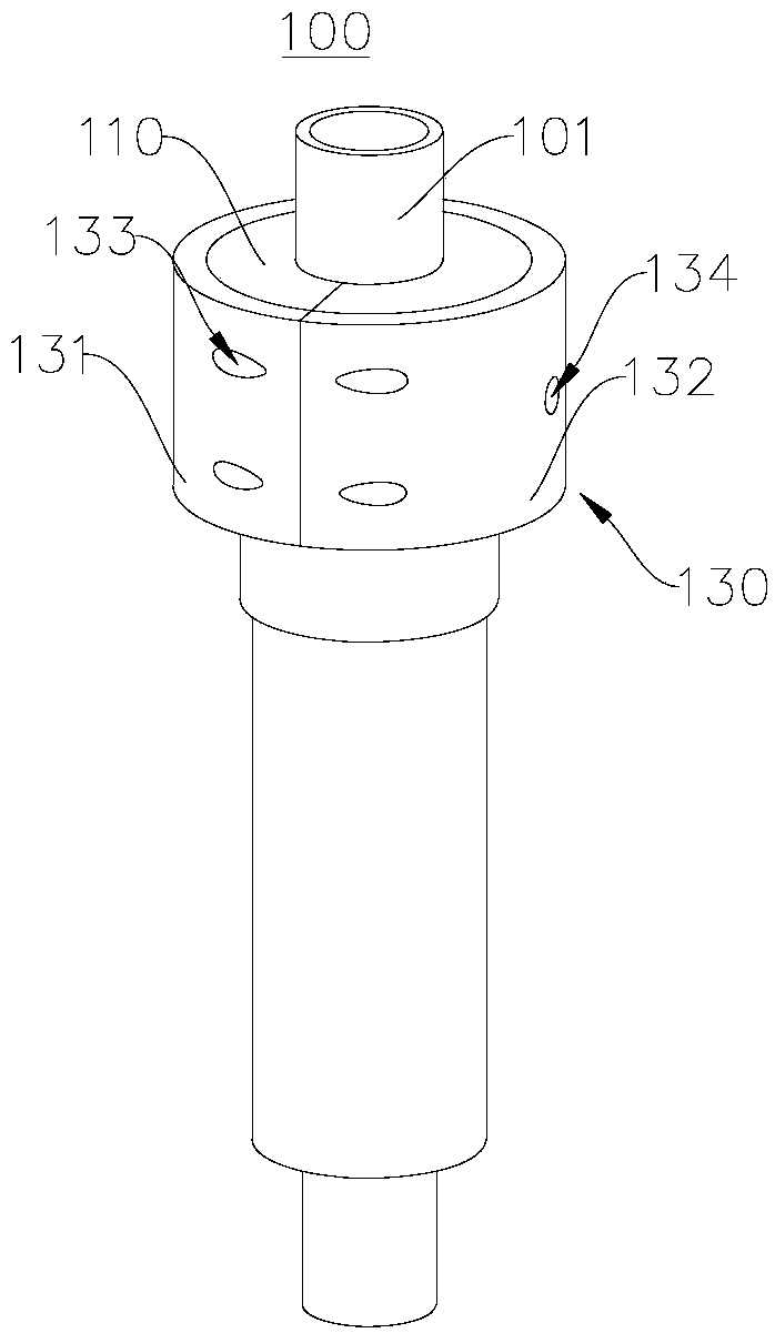
[0037] figure 1 shows a schematic structural view of the gas well plugging device 100 provided by the embodiment of the present invention, please refer to figure 1 . This embodiment provides a gas well plugging device 100, which is mainly used for leakage at the wellhead annular steel plate of a coalbed gas well. It can be understood that the application of the gas well plugging device 100 is not limited in the present invention.

[0038] In this embodiment, the gas well plugging device 100 includes a first snap ring 110, a second snap ring 120 and a third snap ring 130; the first snap ring 110, the second snap ring 120 and the third snap ring 130 are coaxial set up. The third snap ring 130 is sleeved on the outside of the first snap ring 110 and the second snap ring 120 .

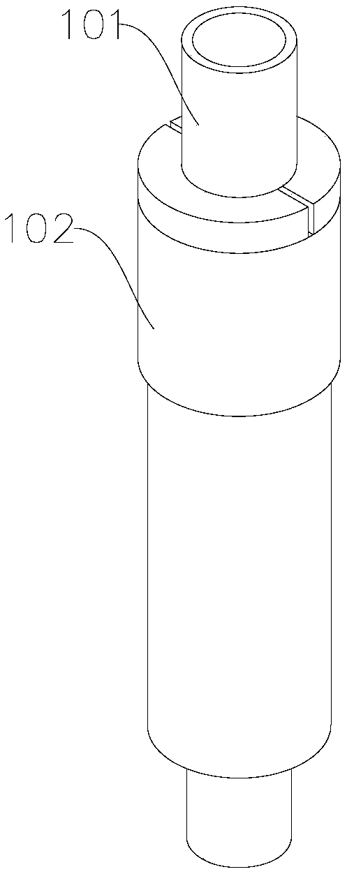
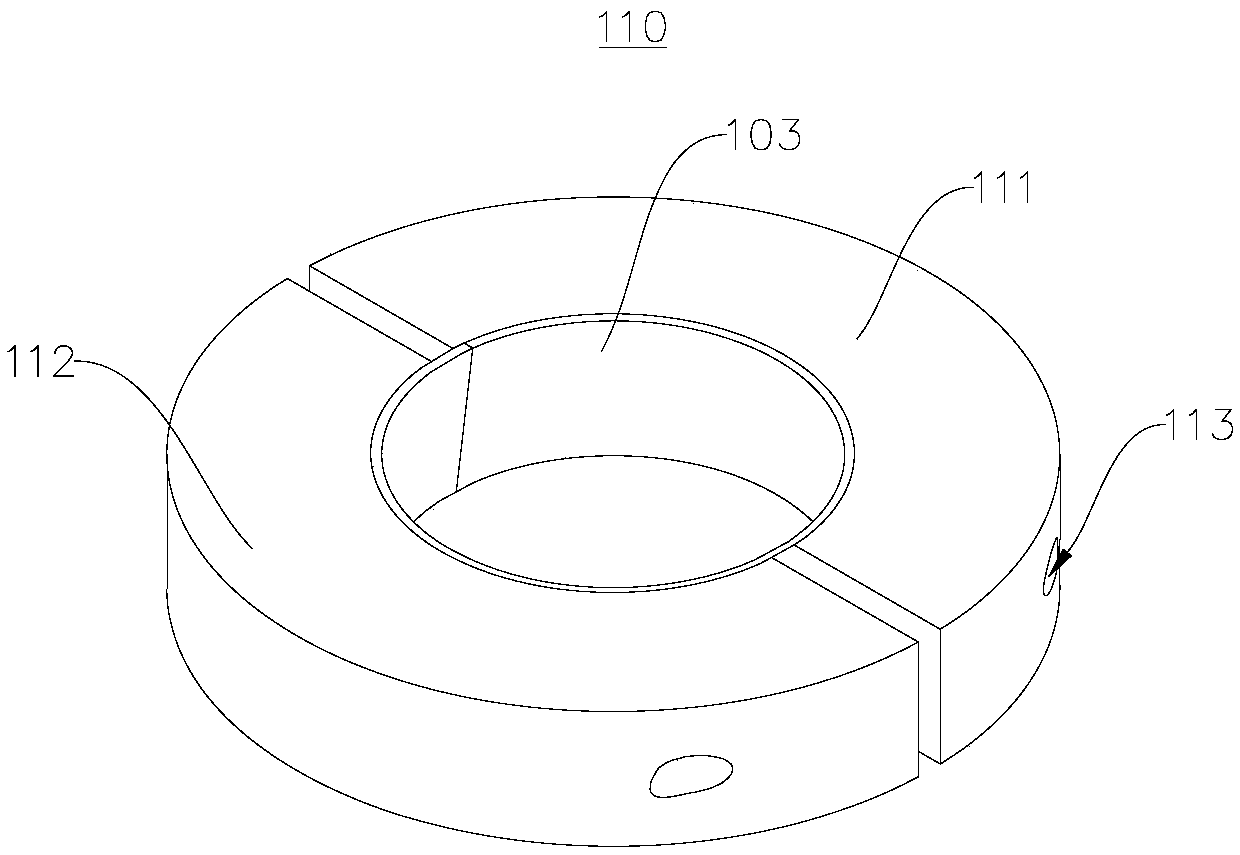
[0039] figure 2 A schematic diagram of the gas well gas production structure is shown, image 3 A schematic structural view of the first clasp 110 provided by the embodiment of the present invention...


PUM


Abstract

The invention relates to the field of gas well equipment and in particular relates to a gas well leaking stoppage device and gas well drilling equipment. The gas well leaking stoppage device comprisesa first clamping ring, a second clamping ring and a third clamping ring, wherein the first clamping ring is matched with a production casing; the first clamping ring comprises a first arc part and asecond arc part in detachable connection; the second clamping ring is matched with a surface casing and comprises a third arc part and a fourth arc part in detachable connection; the third clamping ring is arranged between the first clamping ring and the second clamping ring in a sleeving manner; and the third clamping ring comprises a fifth arc part and a sixth arc part. The first clamping ring is clamped outside the production casing, the second clamping ring is clamped outside the surface casing, and the third clamping ring is fastened with the first clamping ring and the second clamping ring, so that the leaking stoppage effect can be achieved. Coal-bed gas leakage at the annular steel plate at the wellhead of a coal-bed gas well is subjected to emergency maintenance, the welding operation is avoided, the possibility of a flash explosion accident is fundamentally eliminated, and the security risk of welding operators is reduced.

Description

technical field [0001] The invention relates to the field of gas well equipment, in particular to a gas well plugging device and gas well drilling equipment. Background technique [0002] The production life of CBM wells is long, with an average of more than 15 years. Due to the unique well structure of CBM wells, there is no cement sheath outside the production casing in the free section, and the outside of the production casing in the free section is directly connected with the formation. At the same time, the annular steel plate has the function of Single, it can only hang the production casing, and has no function of sealing the annular space between the surface casing and the production casing. Due to the influence of corrosion, casing damage, poor cementing quality, etc. , it is very easy for coalbed methane to migrate from the annular space between the surface casing and the production casing to the annular steel plate at the wellhead, and leak at the wellhead. [00...

Claims


Application Information

Patent Timeline
Patent Type & Authority Applications(China)
IPC IPC(8): E21B33/03
CPCE21B33/03
Inventor 杨福苗马信缘李鹏飞霍轩白楠孙聪
Owner 杨福苗
Why Eureka
Try Eureka