
Corrugated case flattening machine

A corrugated box and flattening machine technology, applied in the field of flattening machines, can solve the problems of low flattening efficiency and inconvenient recycling of corrugated boxes, and achieve the effect of simple structure and wide applicability

Inactive Publication Date: 2018-10-30
TIANJIN MAOHAI YONGTAI PAPER PROD
View PDF6 Cites 5 Cited by
  • Summary
  • Abstract
  • Description
  • Claims
  • Application Information

AI Technical Summary

Problems solved by technology

[0004] The purpose of the present invention is to solve the problems in the prior art that the flattening efficiency is low and it is inconvenient to recycle corrugated boxes in the later stage, and the proposed corrugated box flattening machine

Method used


Image

  • Corrugated case flattening machine
  • Corrugated case flattening machine

Examples


Embodiment Construction

[0019] The following will clearly and completely describe the technical solutions in the embodiments of the present invention with reference to the accompanying drawings in the embodiments of the present invention. Obviously, the described embodiments are only some, not all, embodiments of the present invention.

[0020] In describing the present invention, it should be understood that the terms "upper", "lower", "front", "rear", "left", "right", "top", "bottom", "inner", " The orientation or positional relationship indicated by "outside", etc. is based on the orientation or positional relationship shown in the drawings, and is only for the convenience of describing the present invention and simplifying the description, rather than indicating or implying that the referred device or element must have a specific orientation, so as to Specific orientation configurations and operations, therefore, are not to be construed as limitations on the invention.

[0021] refer to Figure ...


PUM


Abstract

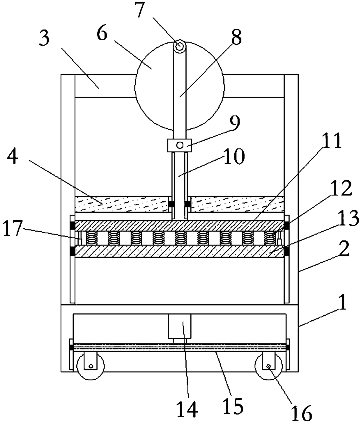
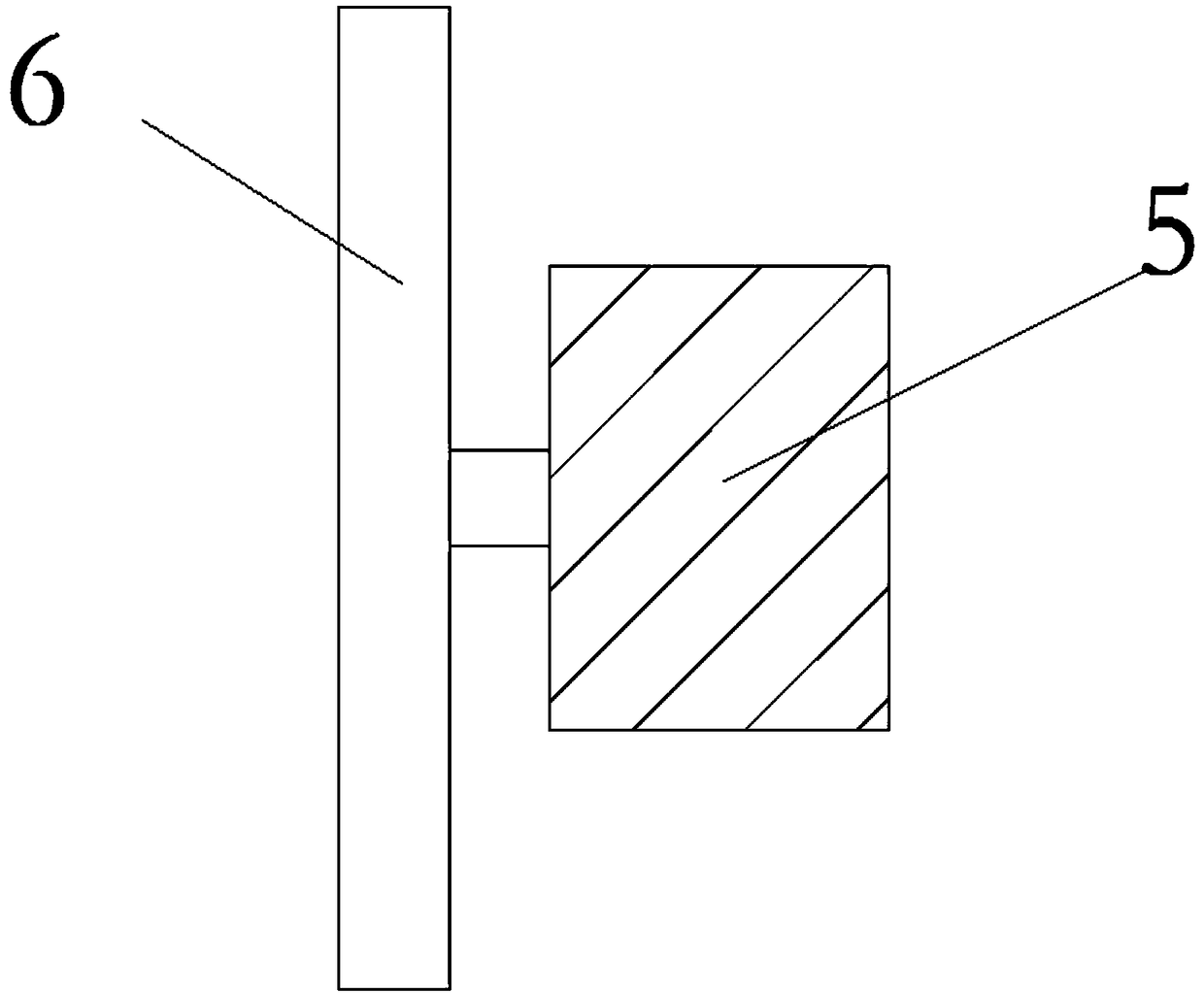
The invention discloses a corrugated case flattening machine which comprises a base. Two vertical plates are fixedly connected to the upper end of the base symmetrically. A supporting rod and a supporting plate close to the center of the vertical plates are fixedly connected to the opposite sides of the two vertical plates up and down. A motor is fixedly connected to one side of the supporting rod. An output shaft of the motor is fixedly connected with a rotating disc. The side, away from the motor, of the rotating disc is fixedly connected with an eccentric rod vertically. The rod wall of theeccentric rod is connected with an eccentric rotating rod in a rotating manner through a ball bearing. The end, away from the eccentric rod, of the eccentric rotating rod is connected with a liftingrod in a rotating manner through a U-shaped clamping plate. The lower end of the lifting rod penetrates the lower end of the supporting plate through a through hole formed in the center of the surfaceof the supporting plate and is fixedly connected with a fixing plate. The lower end of the fixing plate is fixedly connected with a pressing plate through multiple buffering springs. The corrugated case flattening machine can flatten a corrugated case fast and conveniently, and is simple in structure, applicable to small-scale production or individual use and convenient to move.

Description

technical field [0001] The invention relates to the technical field of flattening machines, in particular to a flattening machine for corrugated cartons. Background technique [0002] Corrugated boxes are rigid paper containers made of corrugated cardboard. Corrugated cardboard is die-cut, creasing, stapled or glued. Corrugated carton is the most widely used packaging product, and its consumption has always been the first among all kinds of packaging products. Including calcium plastic corrugated box. [0003] Various corrugated boxes are used in existing social life. In some cases, such as recycling of corrugated boxes, it is necessary to flatten the corrugated boxes as much as possible for later transportation and other operations. Corrugated box flattening machines are mostly large-scale flattening machines used by enterprises, which are not suitable for small-scale production or individual use, and the economy is poor. Low, it is not convenient for later operations s...

Claims


Application Information

Patent Timeline
IPC IPC(8): B31B50/74
CPCB31B50/74
Inventor 郑灼燕
Owner TIANJIN MAOHAI YONGTAI PAPER PROD
Learn More