
Tilting three-axis composite wing unmanned aerial vehicle and control method thereof

A technology of unmanned aerial vehicles and compound wings, which is applied in the field of unmanned aerial vehicles, can solve the problems of strict take-off and landing sites, large self-load, unstable flight attitude, etc., and achieve the advantages of improving flexible operation, reducing power loss, and low investment cost Effect

Pending Publication Date: 2018-10-26
CHINA JK INST OF ENG INVESTIGATION & DESIGN
View PDF4 Cites 8 Cited by
  • Summary
  • Abstract
  • Description
  • Claims
  • Application Information

AI Technical Summary

Problems solved by technology

At present, the mainstream models in the field of civilian UAVs can be divided into the following types: pure fixed-wing UAVs, pure rotor UAVs, and hybrid-wing UAVs. Wing UAVs require a wide range of clearance, strict take-off and landing sites, and problems with take-off and landing safety; pure rotor UAVs have high power consumption and low efficiency; hybrid-wing UAVs have the disadvantages of large volume, unstable flight attitude, and large self-load

Method used


Image

  • Tilting three-axis composite wing unmanned aerial vehicle and control method thereof
  • Tilting three-axis composite wing unmanned aerial vehicle and control method thereof
  • Tilting three-axis composite wing unmanned aerial vehicle and control method thereof

Examples


Embodiment Construction

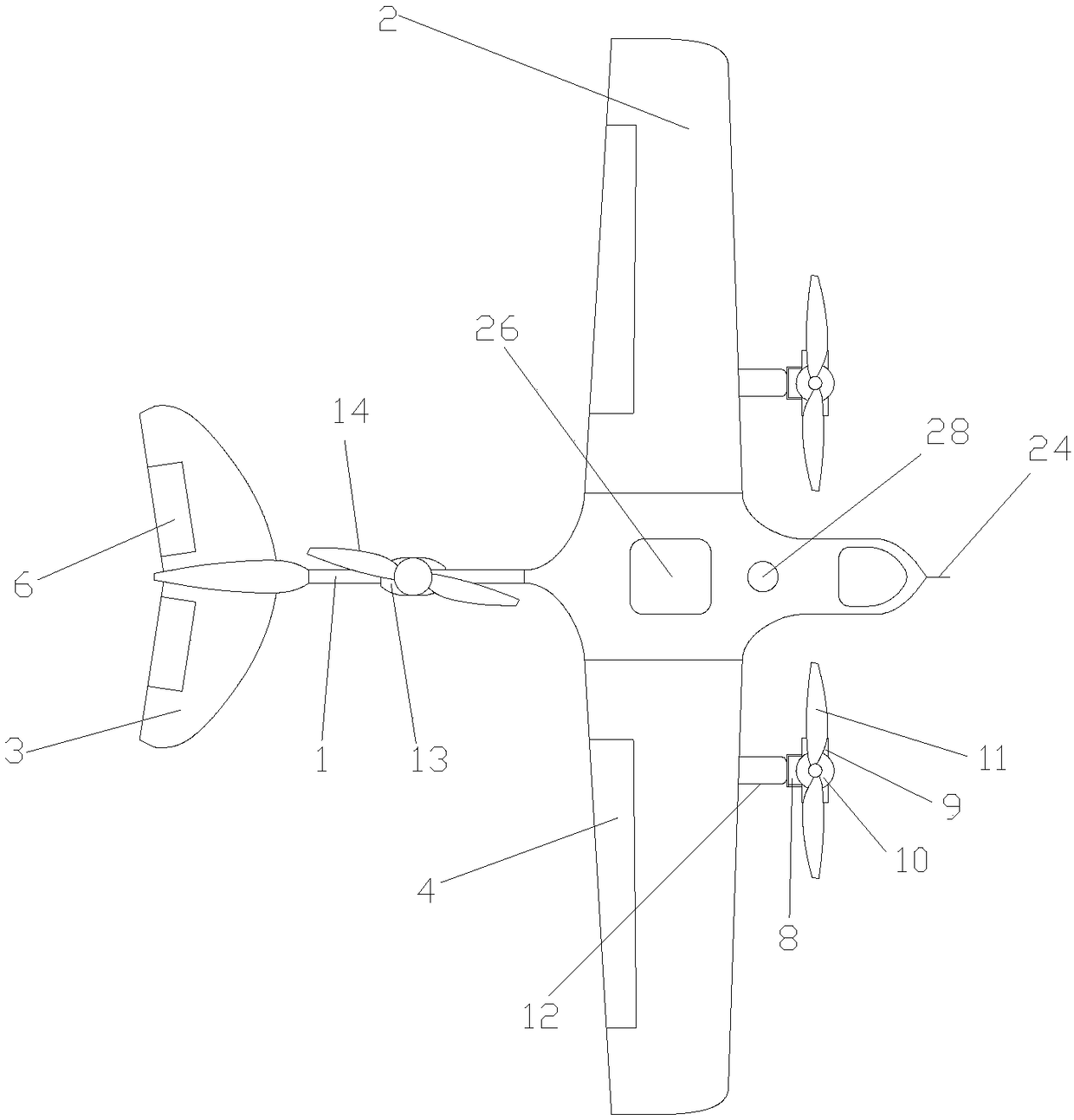
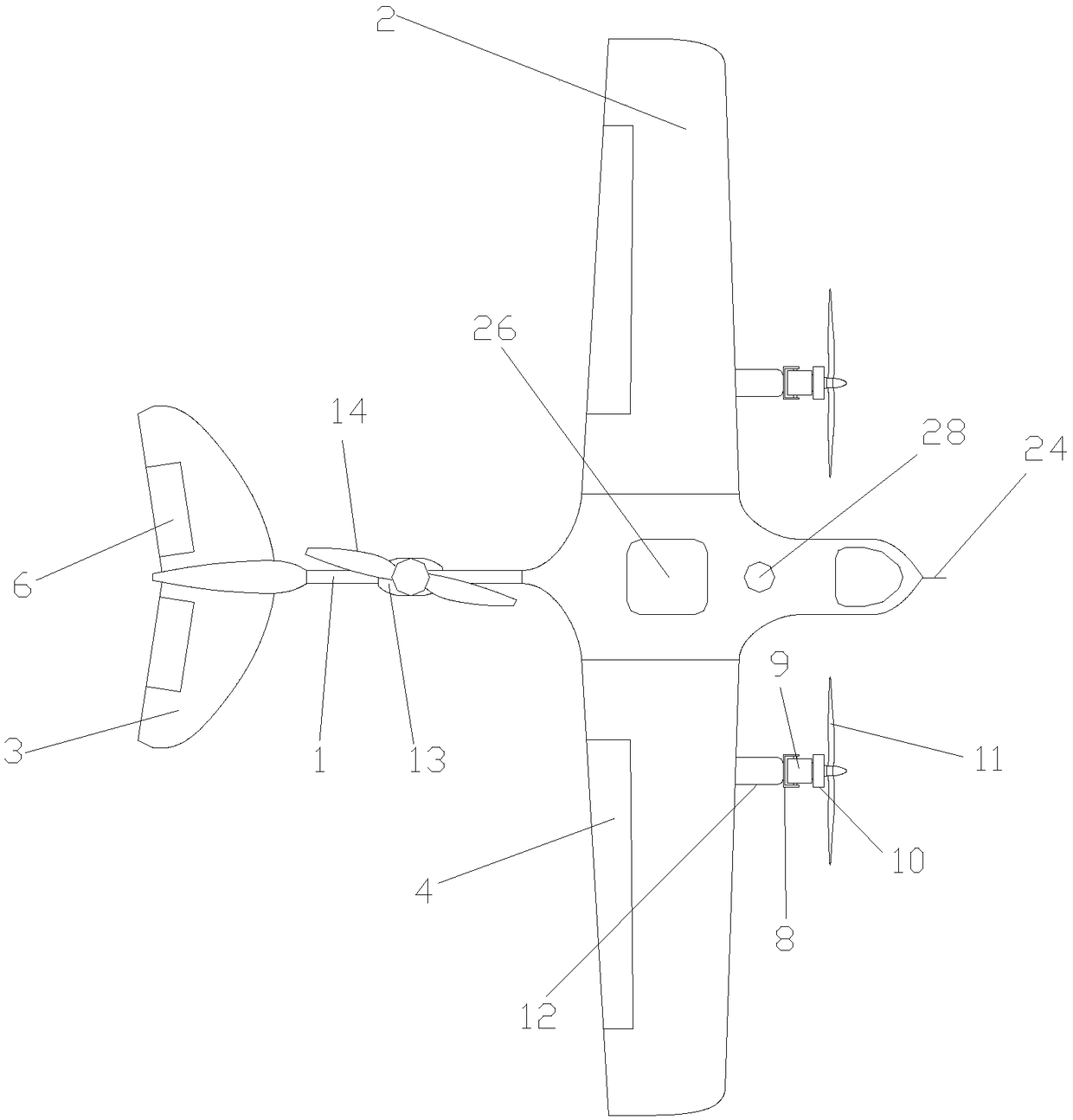
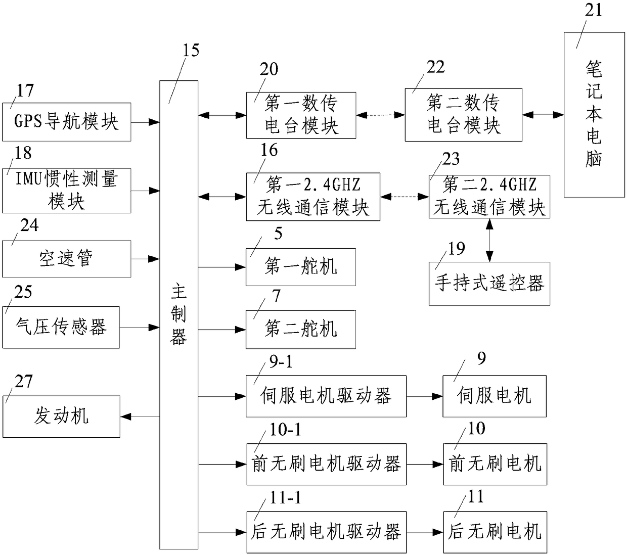
[0060] Such as figure 1 , figure 2 and image 3 A kind of tilting three-axis compound-wing unmanned aerial vehicle shown, comprises body 1, the fixed-wing mechanism that is installed on the body 1, the rotary-wing power mechanism that is arranged on described fixed-wing mechanism and described fixed-wing mechanism and a control module for controlling the rotor power mechanism, and a ground station monitoring terminal for wireless communication with the control module;

[0061] The fixed wing mechanism includes a main wing 2 installed on the front of the body 1 and arranged symmetrically along the length direction of the body 1, and an empennage 3 symmetrically installed at the tail of the body 1. The main wing 2 is provided with a first aileron 4, and the main wing 2 is provided with a first steering gear 5 that drives the first aileron 4 to rotate, and the empennage 3 is provided with a second aileron 6, and the empennage 3 is provided with a second steering gear that driv...


PUM


Abstract

The invention discloses a tilting three-axis composite wing unmanned aerial vehicle and a control method thereof. The tilting three-axis composite wing unmanned aerial vehicle comprises a vehicle body, a fixed-wing mechanism, a rotor-wing power mechanism, a control module and a ground station monitoring terminal; the fixed-wing mechanism comprises a main wing and an empennage; and the rotor-wing power mechanism comprises two front tilting power mechanisms and a rear rotor-wing power mechanism body. The control method comprises the following steps that 1, the flight parameters of the unmanned aerial vehicle are set; 2, the tilting three-axis composite wing unmanned aerial vehicle ascends vertically; 3, the front tilting power mechanisms rotate, and the tilting three-axis composite wing unmanned aerial vehicle flies horizontally; 4, the tilting three-axis composite wing unmanned aerial vehicle makes a return voyage and descends spirally; and 6, the tilting three-axis composite wing unmanned aerial vehicle descends vertically. The tilting three-axis composite wing unmanned aerial vehicle is reasonable in design and small in size, by arranging the front tilting power mechanisms, vertical ascending can be achieved, horizontal flying can further be achieved, the load is small, energy consumption is small, flying is stable, and practicality is high.

Description

technical field [0001] The invention belongs to the technical field of unmanned aerial vehicles, and in particular relates to a tilting three-axis compound-wing unmanned aerial vehicle and a control method thereof. Background technique [0002] UAV, referred to as UAV, is an aircraft with autonomous navigation or remote control or both. It was born during the First World War in the early 20th century. The purpose of its development was to reduce aircraft crashes and pilot sacrifices, and thus enable long-range unmanned attacks. In the 21st century, with the advancement of science and technology, UAV technology and industry have developed rapidly, and have been widely used in various industries. Military missions can perfectly replace manned aircraft to perform 4D (Dull, Dirty, Dangerous, Deep) missions; civilian use UAVs are widely used in various fields such as industry, agriculture, and service industries. At present, the mainstream models in the field of civilian UAVs c...

Claims


Application Information

Patent Timeline
Patent Type & Authority Applications(China)
IPC IPC(8): B64C27/28B64C9/06B64D27/02B64D27/24G05D1/10
CPCG05D1/101B64C9/06B64C27/28B64D27/02B64D27/24B64U10/00B64U50/11B64U50/19B64D27/026
Inventor 杨永林杨超张继文潘东峰郑建国丁吉峰夏玉云赵国梁廖东军杨小梅张腾飞李玮彭卫超
Owner CHINA JK INST OF ENG INVESTIGATION & DESIGN
Learn More