
A rapid stamping forming equipment for auto parts

A technology of auto parts and stamping forming, which is applied in the direction of vehicle parts, forming tools, metal processing equipment, etc., can solve the problems affecting the quality of auto parts forming, the position deviation of raw materials, and the low production efficiency of auto parts

Active Publication Date: 2020-04-28
南京星瑞汽车部件有限公司
View PDF5 Cites 0 Cited by
  • Summary
  • Abstract
  • Description
  • Claims
  • Application Information

AI Technical Summary

Problems solved by technology

[0002] In the production process of auto parts, stamping machines must be used. However, the stamping machines currently used for the production of auto parts have the following disadvantages: 1. When the stamping machines currently used for the production of auto parts stamp raw materials, when the When the stamping die and the lower stamping die are clamped, the raw materials placed on the lower stamping die are prone to position deviation, which will easily affect the molding quality of auto parts; 2. The stamping machine currently used to produce auto parts After stamping the raw materials, it is necessary to manually remove the stamped auto parts from the lower stamping die. , the stamping machine is easy to hurt the staff, and there is a great safety hazard; 3. When the stamping machine used to produce auto parts stamps the raw materials, it needs to manually place the raw materials on the stamping die. The disadvantage of low production efficiency of parts, and the method of manually placing raw materials on the stamping die. When the stamping machine stamps the raw materials, the stamping machine is easy to hurt the staff, and there is a great potential safety hazard

Method used


Image

  • A rapid stamping forming equipment for auto parts
  • A rapid stamping forming equipment for auto parts
  • A rapid stamping forming equipment for auto parts

Examples


Embodiment Construction

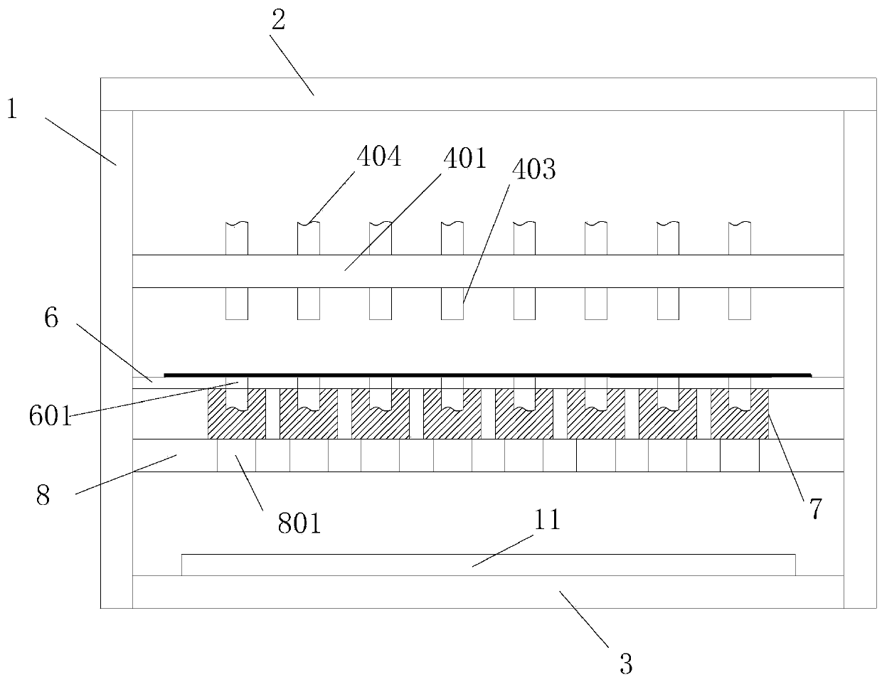
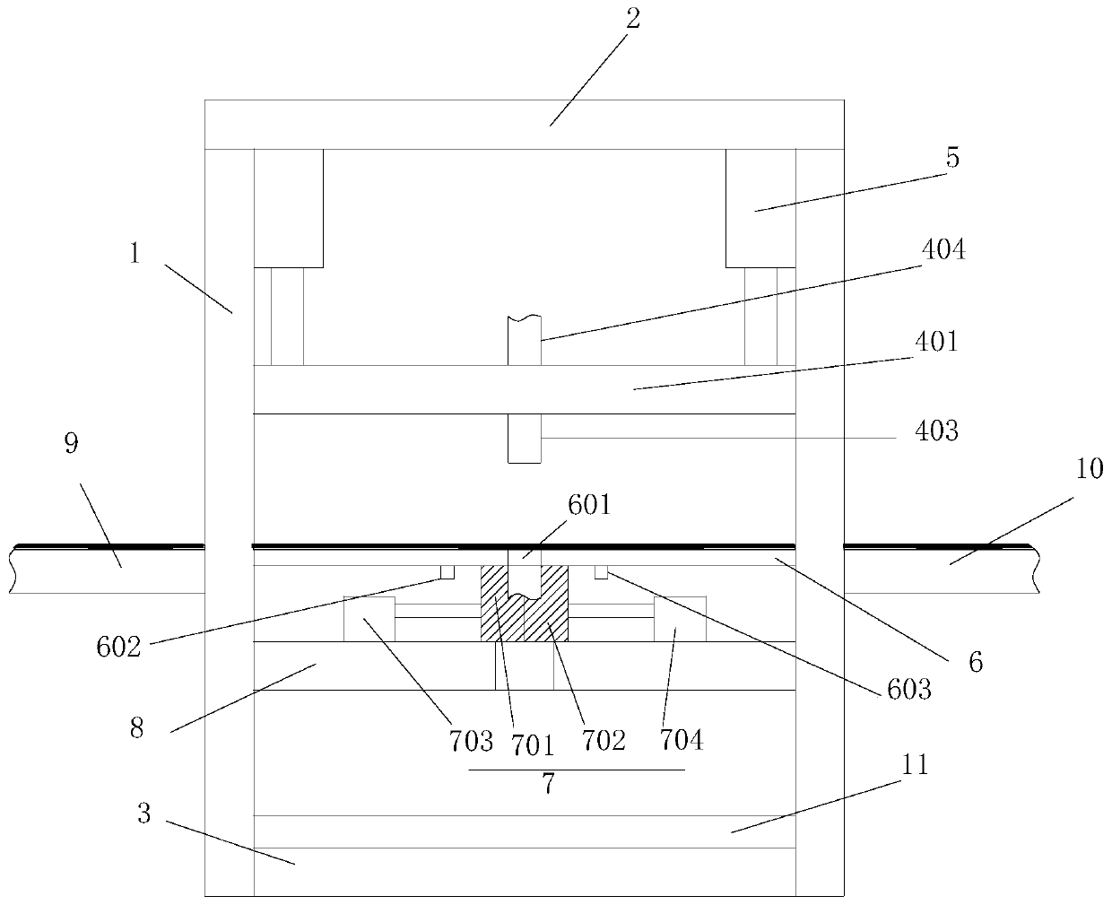
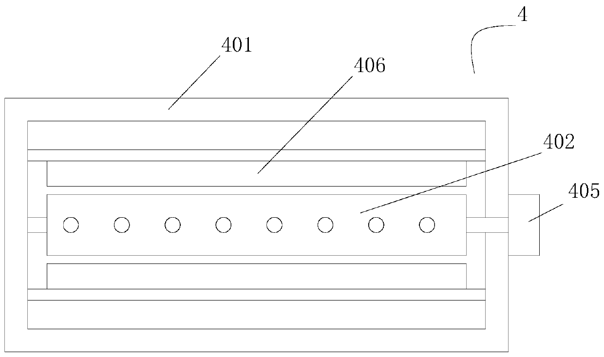
[0019] Such as Figure 1-Figure 3 as shown, figure 1 It is a structural schematic diagram of a rapid stamping forming equipment for auto parts proposed by the present invention; figure 2 It is a side view of a rapid stamping forming equipment for auto parts proposed by the present invention; image 3 It is a top view of the mold base in the rapid stamping forming equipment for auto parts proposed by the present invention.

[0020] refer to Figure 1-Figure 3 , a kind of rapid stamping and forming equipment for auto parts proposed by the present invention, comprising a frame 1, a first working frame 2, a second working frame 3, a mold frame 4, a first driving mechanism 5, a guide plate 6, and a plurality of forming dies 7. The blanking plate 8, the first transmission mechanism 9, the second transmission mechanism 10 and the third transmission mechanism 11; wherein:

[0021] The first work frame 2 and the second work frame 3 are arranged in parallel up and down and the firs...


PUM


Abstract

The invention discloses automobile part rapid punch forming equipment. The equipment comprises a rack, a first work support, a second work support, a die support, a first drive mechanism, a guide plate, a plurality of forming dies and a discharging plate. The die support comprises a die frame, a die plate, a plurality of cutting puncher pins, a plurality of forming puncher pins and a second drivemechanism. Guide holes are formed in the guide plate in the length direction of the guide plate at intervals and penetrate through the upper and lower surfaces of the guide plate. A plurality of discharging holes are formed in the discharging plate in the length direction of the discharging plate at intervals and penetrate through the upper and lower surfaces of the discharging plate. Each formingdie comprises a first movable die body, a second movable die body, a third drive mechanism and a fourth drive mechanism. According to the automobile part rapid punch forming equipment, by arranging the guide plate and forming the guide holes, raw materials are positioned and guided, semi-finished products are prevented from shifting, an the automobile part forming quality is improved; by arranging the forming dies and the discharging plate, products subjected to punch forming are automatically discharged; and by arranging a first conveying mechanism and a second conveying mechanism, the raw materials are automatically fed, and the production efficiency is further improved.

Description

technical field [0001] The invention relates to the technical field of auto parts processing, in particular to a rapid stamping forming equipment for auto parts. Background technique [0002] In the production process of auto parts, stamping machines must be used. However, the stamping machines currently used for the production of auto parts have the following disadvantages: 1. When the stamping machines currently used for the production of auto parts stamp raw materials, when the When the stamping die and the lower stamping die are clamped, the raw materials placed on the lower stamping die are prone to position deviation, which will easily affect the molding quality of auto parts; 2. The stamping machine currently used to produce auto parts After stamping the raw materials, it is necessary to manually remove the stamped auto parts from the lower stamping die. , the stamping machine is easy to hurt the staff, and there is a great safety hazard; 3. When the stamping machine...

Claims


Application Information

Patent Timeline
Patent Type & Authority Patents(China)
IPC IPC(8): B21D53/88B21D35/00B21D43/00B21D43/02B21D37/06
CPCB21D35/002B21D37/06B21D43/003B21D43/027B21D53/88
Inventor 潘凤华
Owner 南京星瑞汽车部件有限公司
Learn More