
A stamping machine for processing auto parts

A technology of auto parts and stamping machines, applied in the field of stamping machines, can solve the problems affecting the forming quality of auto parts, the position deviation of raw materials, and the low production efficiency of auto parts

Active Publication Date: 2020-06-05
CHONGQING CHANGAN SUOQI AUTO PARTS
View PDF4 Cites 0 Cited by
  • Summary
  • Abstract
  • Description
  • Claims
  • Application Information

AI Technical Summary

Problems solved by technology

[0002] In the production process of auto parts, stamping machines must be used. However, the stamping machines currently used for the production of auto parts have the following disadvantages: 1. When the stamping machines currently used for the production of auto parts stamp raw materials, when the When the stamping die and the lower stamping die are clamped, the raw materials placed on the lower stamping die are prone to position shifting, which will easily affect the molding quality of auto parts; 2. The stamping machine currently used to produce auto parts After stamping the raw materials, it is necessary to manually remove the stamped auto parts from the lower stamping die. , the stamping machine is easy to hurt the staff, and there is a great potential safety hazard

Method used


Image

  • A stamping machine for processing auto parts
  • A stamping machine for processing auto parts

Examples


Embodiment Construction

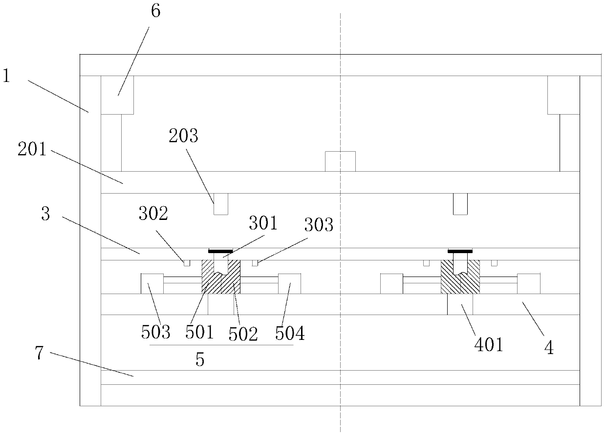
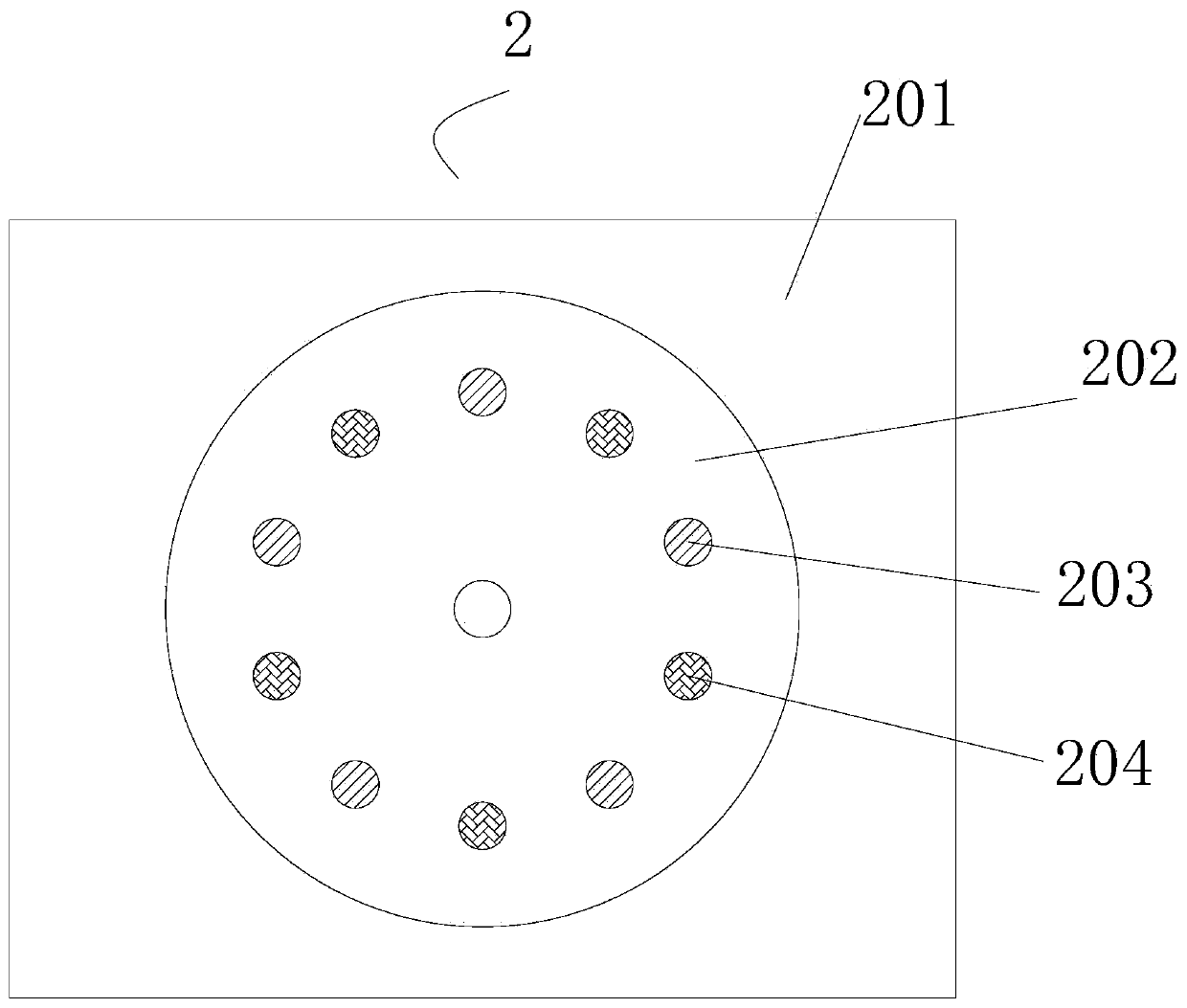
[0016] Such as Figure 1-Figure 2 as shown, figure 1 It is a structural schematic diagram of a stamping machine for processing auto parts proposed by the present invention; figure 2 It is a structural schematic diagram of a die base in a stamping machine for processing auto parts proposed by the present invention.

[0017] refer to Figure 1-Figure 2 , a stamping machine for processing auto parts proposed by the present invention, including a frame 1, a mold frame 2, a guide plate 3, a blanking plate 4, N forming dies 5, a first driving mechanism 6 and a transmission mechanism 7 , N is a positive integer; where:

[0018] The mold frame 2 includes a mold frame 201, a template 202, N cutting punches 203, N forming punches 204 and a second drive mechanism 205, the mold frame 201 is arranged horizontally, and the mold frame 201 is movably installed on the frame 1 and is controlled by The first drive mechanism 6 is driven to move up and down in the vertical direction. The temp...


PUM


Abstract

The invention discloses a punching machine for machining automobile parts. The punching machine for machining the automobile parts comprises a rack, a die set, a guide plate, a blanking plate, N forming dies and a first drive mechanism. The die set comprises a die frame, a die plate, N cutting plunger chips, N forming plunger chips and a second drive mechanism. The die plate is arranged in the dieframe and is rotationally connected with the die frame. The second drive mechanism is connected with the die plate and used for driving the die plate to rotate. The N cutting plunger chips are installed below the die plate and are evenly distributed along a circumference. The N forming plunger chips are installed below the die plate and are evenly distributed along a circumference. The guide plate is provided with N guide holes which are evenly distributed along a circumference and penetrate through the upper surface and the lower surface of the guide plate. The blanking plate is located below the guide plate and is parallel to the guide plate. The N forming dies are arranged between the blanking plate and the guide plate and are evenly distributed along a circumference. According to thepunching machine for machining the automobile parts, the guide plate and the guide holes are arranged to position and guide a raw material, semi-finished product skewing is prevented, and the formingquality of the automobile parts is improved.

Description

technical field [0001] The invention relates to the technical field of auto parts processing, in particular to a stamping machine for processing auto parts. Background technique [0002] In the production process of auto parts, stamping machines must be used. However, the stamping machines currently used for the production of auto parts have the following disadvantages: 1. When the stamping machines currently used for the production of auto parts stamp raw materials, when the When the stamping die and the lower stamping die are clamped, the raw materials placed on the lower stamping die are prone to position deviation, which will easily affect the molding quality of auto parts; 2. The stamping machine currently used to produce auto parts After stamping the raw materials, it is necessary to manually remove the stamped auto parts from the lower stamping die. , The stamping machine is easy to hurt the staff, and there is a great potential safety hazard. Contents of the inven...

Claims


Application Information

Patent Timeline
Patent Type & Authority Patents(China)
IPC IPC(8): B21D35/00B21D45/02
CPCB21D35/002B21D45/02
Inventor 潘凤华
Owner CHONGQING CHANGAN SUOQI AUTO PARTS
Learn More