
Industrial waste gas pollution management device

A technology for pollution control and industrial waste gas, applied in the direction of gas treatment, use of liquid separation agent, membrane technology, etc., can solve the problems of waste of neutralization liquid and troublesome operation

Inactive Publication Date: 2018-10-26
JIXINGYUAN TIANJIN ENVIRONMENTAL PROTECTION TECH CO LTD
View PDF0 Cites 5 Cited by
  • Summary
  • Abstract
  • Description
  • Claims
  • Application Information

AI Technical Summary

Problems solved by technology

[0002] In the process of industrial production, some waste gas and some waste particles are often produced, and some small waste particles will be discharged together with the waste gas. Because the waste gas and waste particles will be acidic, these waste gas and waste particles are discharged into the air. It will have a great impact on the surrounding environment, and with the continuous improvement of people's environmental awareness, the country also imposes strict requirements on some factories to ensure that the gas discharged into the air will not pollute the surrounding environment. Traditional waste gas treatment will The exhaust gas is passed into the neutralizing liquid, thereby reducing the emission of harmful substances into the air. Since the waste particles will stay in the liquid when passing through the liquid, deposits will be formed. After the deposits continue to increase, the deposits need to be removed Timely discharge, because the traditional treatment equipment needs to discharge the liquid before cleaning the sediment when discharging the waste particles, on the one hand, it will cause waste of neutralization liquid, on the other hand, the operation is troublesome

Method used


Image

  • Industrial waste gas pollution management device

Examples


Embodiment Construction

[0019] All the features disclosed in this specification, or all disclosed methods or steps in the process, except for mutually exclusive features and / or steps, can be combined in any manner.

[0020] Any feature disclosed in this specification, unless specifically stated, can be replaced by other equivalent or equivalent alternative features. That is, unless otherwise stated, each feature is just one example of a series of equivalent or similar features.

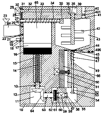
[0021] Such as figure 1 As shown, an industrial waste gas pollution treatment device of the device of the present invention includes a body 10 in which a processing chamber 65 is provided, and a sliding groove is connected to the bottom wall of the processing chamber 65. A piston block 16 that can slide up and down is installed, and a first sliding block 15 that can slide up and down and is fixedly connected to the piston block 16 is installed in the sliding groove. The first sliding block 15 is provided with an opening facing d...


PUM


Abstract

The invention discloses an industrial waste gas pollution management device. The industrial waste gas pollution management device comprises a machine body, wherein a treatment cavity is arranged in the machine body; a sliding groove is formed in a bottom wall of the treatment cavity in a communication manner; a piston block capable of sliding up and down is mounted in the treatment cavity; the sliding groove is internally provided with a first sliding block which can slide up and down and is fixedly connected with the piston block; a thread groove with a downward opening is formed in the firstsliding block; a first thread rod is mounted in the thread groove in a matching manner; a first transmission cavity is arranged below the sliding groove; a first rotary shaft is rotatably mounted between the first transmission cavity and the sliding groove; the upper end of the first rotary shaft is fixedly connected with the first thread rod and the lower end of the first rotary shaft stretchesinto the first transmission cavity and is fixedly provided with a first bevel gear; a drying cavity is arranged at the right side of the treatment cavity; first through grooves which are mutually communicated are formed in the upper part of the drying cavity and the upper part of the treatment cavity; a second transmission cavity, which extends upward, is formed in a left end wall of the treatmentcavity.

Description

Technical field [0001] The invention relates to the technical field of environmental protection, in particular to an industrial waste gas pollution treatment device. Background technique [0002] In the industrial production process, some waste gas and some waste particles are often produced. Some small waste particles will be discharged together with the waste gas. Because the waste gas and waste particles will be acidic, these waste gas and waste particles are discharged into the air. Will have a great impact on the surrounding environment, and with the continuous improvement of people’s environmental awareness, the state has also imposed strict requirements on some factories to ensure that the gas discharged into the air will not pollute the surrounding environment. Traditional waste gas treatment will Exhaust gas is passed into the neutralization liquid, thereby reducing the emission of harmful substances into the air. Because the waste particles will stay in the liquid when...

Claims


Application Information

Patent Timeline
Patent Type & Authority Applications(China)
IPC IPC(8): B01D47/02B01D53/78B01D53/40B01D53/73
CPCB01D47/02B01D53/40B01D53/73B01D53/78B01D2258/02
Inventor 许瑶
Owner JIXINGYUAN TIANJIN ENVIRONMENTAL PROTECTION TECH CO LTD
Learn More