
An Inversion Method of In-situ Stress Field Based on 3D Modeling

A technology of three-dimensional modeling and stress field, which is applied in the field of geological survey, can solve the problems of costing money, few measuring points, and difficulty in achieving large-scale projects, and achieve the effect of reducing the workload on site

Active Publication Date: 2020-07-03
TAIYUAN UNIV OF TECH
View PDF5 Cites 0 Cited by
  • Summary
  • Abstract
  • Description
  • Claims
  • Application Information

AI Technical Summary

Problems solved by technology

At present, the on-site stress testing methods include hydraulic fracturing method, stress relief method, drilling caving method, etc. Laboratory tests include acoustic emission method, rock micro-crack closure deformation critical stress method, etc. However, on-site rock mass stress testing is a time-consuming process. The laborious and financially consuming complex work has limited the popularization and application of on-site rock mass stress testing to a certain extent. At the same time, the measured values ​​can only represent the stress conditions within a certain range near the measuring points, and the limited measuring points cannot reflect the overall stress field of the region.
In this case, it is very necessary to find an intuitive and effective method to reflect the overall in-situ stress characteristics of underground engineering. Inversion of structural in-situ stress through 3D numerical simulation software is one of the effective ways. At the same time, when using 3D numerical simulation software to invert the in-situ stress, the 3D model established is often small in size in order to balance the calculation speed and calculation accuracy, and it is difficult to achieve large-scale engineering, and the actual calculation effect and accuracy will be limited. At the same time, it is also a difficult problem to conveniently and quickly establish a 3D numerical model with structures and perform effective inversion of the in-situ stress field

Method used


Image

  • An Inversion Method of In-situ Stress Field Based on 3D Modeling
  • An Inversion Method of In-situ Stress Field Based on 3D Modeling
  • An Inversion Method of In-situ Stress Field Based on 3D Modeling

Examples


Embodiment Construction

[0020] The technical solutions of the present invention will be further described in more detail below in conjunction with specific embodiments. Apparently, the described embodiments are only some of the embodiments of the present invention, not all of them. Based on the embodiments of the present invention, all other embodiments obtained by persons of ordinary skill in the art without creative efforts shall fall within the protection scope of the present invention.

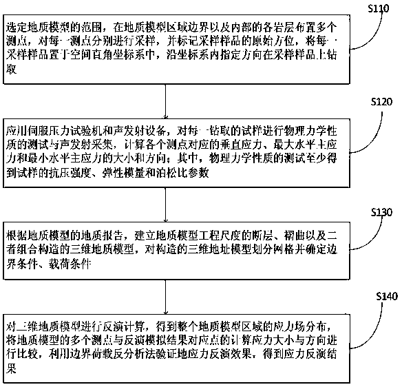
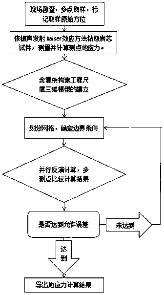
[0021] refer to figure 1 with figure 2 , figure 1 It is a schematic flow chart of a three-dimensional modeling-based geostress field inversion method provided by the present invention; figure 2 It is a schematic diagram of a three-dimensional modeling-based geostress field inversion method provided by the present invention. The steps of the method include:

[0022] S110: Select the scope of the geological model, arrange multiple measuring points on the boundary of the geological model area and each rock la...


PUM


Abstract

The invention discloses a three-dimensional modeling-based ground stress field inversion method. The method only needs to carry out sampling work at the engineering site, which effectively reduces the workload on the site, and can realize sampling at multiple measuring points, and realize multiple ground stresses. Precise measurement of measuring points; a large-scale three-dimensional numerical model with single or complex structures can be established, and the inversion of the in-situ stress distribution characteristics of the inversion study area can be performed through parallel computing; an intuitive and visualized overall in-situ stress distribution can be obtained, effectively Extract and view information such as vertical stress, maximum horizontal principal stress, minimum horizontal principal stress value and direction at different levels, different inclined surfaces, and different structures of the model.

Description

technical field [0001] The invention relates to the field of geological survey, in particular to a three-dimensional modeling-based ground stress field inversion method. Background technique [0002] In-situ stress is the natural stress that exists in the earth's crust without being disturbed by engineering, and the in-situ stress field including structures is often more complex and changeable. Long-term practice has shown that in-situ stress is the fundamental force that causes deformation and destruction of tunnels, surrounding rocks of coal mine roadways, supporting structures, and mine dynamic phenomena. After the tunnel is excavated, the initial stress field and deformation field are redistributed by the excavation disturbance, causing damage to the surrounding rock, and in severe cases, instability, collapse and destruction. When the tunnel is within the influence range of the geological structure , the influence of the structure on the stress field is especially obvi...

Claims


Application Information

Patent Timeline
Patent Type & Authority Patents(China)
IPC IPC(8): G01V99/00G01N3/08G01N29/14
CPCG01N3/08G01N29/14G01V20/00
Inventor 段东冯小静任惠亮张百胜康志勤赵凯雷刘文博陈思顺孙江
Owner TAIYUAN UNIV OF TECH
Learn More