
Current measurement techniques to compensate for shunt drift

A shunt resistance and current technology, applied in the field of current measurement equipment, can solve unpredictable problems

Active Publication Date: 2018-10-23
ANALOG DEVICES INT UNLTD CO
View PDF5 Cites 4 Cited by
  • Summary
  • Abstract
  • Description
  • Claims
  • Application Information

AI Technical Summary

Problems solved by technology

However, over the lifetime of a shunt, its value can change independently of temperature, which can be unpredictable
Also, in typical applications, the current through the shunt is continuously monitored, which can present challenges in monitoring the shunt itself
This shunt typically has a resistance of less than 1 ohm, which can add further challenges

Method used


Image

  • Current measurement techniques to compensate for shunt drift
  • Current measurement techniques to compensate for shunt drift
  • Current measurement techniques to compensate for shunt drift

Examples


Embodiment Construction

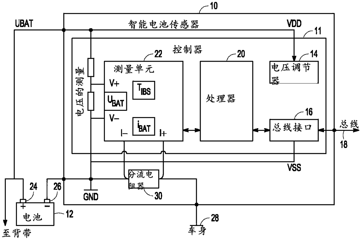
[0022] In intelligent battery sensing (IBS) applications, the state of health (SOH), state of charge (SOC) and state of function (SOF) of the battery can be determined by directly measuring the battery voltage and also measuring the current delivered by the battery in various operating modes. Current is usually measured by placing a current shunt in series with one of the battery terminals and measuring the voltage across it. Application of Ohm's law (current (I) = voltage (V) / resistance (R)) can derive the current. However, for the current measurement to be accurate, the resistance of the current shunt should be known exactly. Initially, the shunt can be measured on the factory floor, and then an offset / gain calibration can be performed on the shunt. Once the part containing the shutdown comes out of the field connected to the battery, there is no efficient way to monitor the value of the shunt itself, since there is always an unknown current (battery current) flowing throug...


PUM


Abstract

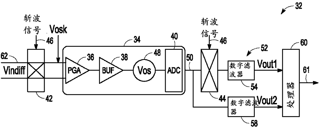
The disclosure relates to current measurement techniques to compensate for shunt drift. Described are various current measurement techniques that can compensate for drift in shunt resistance. Determining a resistance of a shunt resistor, e.g., coupled to a battery terminal, can include introducing a known signal in sync with the chop phases of a dual system chop scheme, chopping the known signal out in the main signal path, and explicitly extracting the known signal in a parallel, additional signal deprocessing path.

Description

technical field [0001] The present disclosure relates to current measurement devices and methods. Background technique [0002] In a shunt-based current measurement setup, current is measured by placing a known low-resistance "shunt" in series with the current to be measured, and then measuring the voltage across the series shunt. Application of Ohm's law (current (I) = voltage (V) / resistance (R)) will result in a current flowing through the shunt. The accuracy of the current measurement depends on the accuracy of the voltage measurement and the resistance accuracy of the shunt itself. [0003] Typically, the system is calibrated at the factory, which can include temperature compensation at multiple temperature points to compensate for the temperature effect of the shunt. For automotive applications, a single temperature calibration is typically used. However, over the lifetime of a shunt, its value can change independently of temperature, which can be unpredictable. Add...

Claims


Application Information

Patent Timeline
Patent Type & Authority Applications(China)
IPC IPC(8): G01R19/25
CPCG01R19/25H01M10/48G01R27/00G01R31/364Y02E60/10G01R19/2506G01R15/146
Inventor A·卡拉南
Owner ANALOG DEVICES INT UNLTD CO
Learn More