
Infrared tire pressure monitoring system and method thereof and vehicle

A tire pressure monitoring and tire pressure technology, applied in tire measurement, vehicle parts, tire parts, etc., can solve the problems of difficult disassembly and difficult battery replacement of sensors

Inactive Publication Date: 2018-10-23
BEIQI FOTON MOTOR CO LTD
View PDF5 Cites 3 Cited by
  • Summary
  • Abstract
  • Description
  • Claims
  • Application Information

AI Technical Summary

Problems solved by technology

This method has many disadvantages, such as: difficulty in disassembly, difficulty in replacing the battery of the sensor, and the need to re-do the dynamic balance test on the tire after replacing the sensor.

Method used

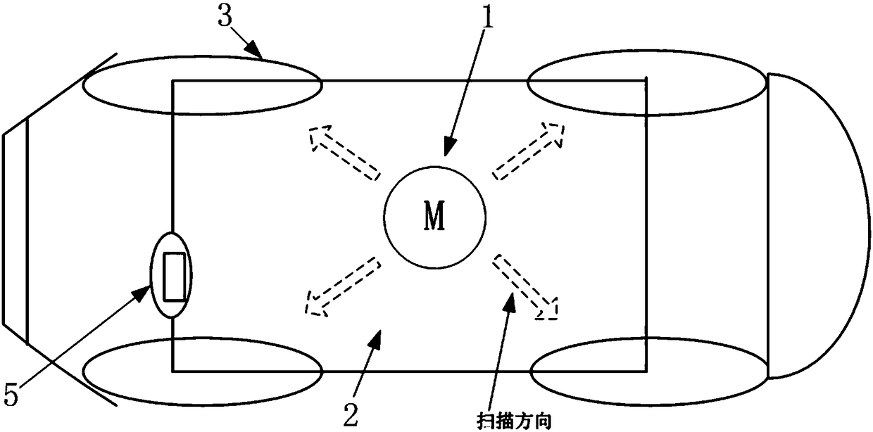
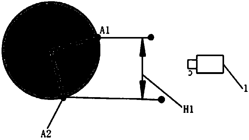
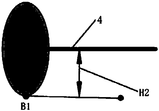

Image

  • Infrared tire pressure monitoring system and method thereof and vehicle
  • Infrared tire pressure monitoring system and method thereof and vehicle
  • Infrared tire pressure monitoring system and method thereof and vehicle

Examples


Embodiment Construction

[0024] In the drawings, the same or similar reference numerals are used to denote the same or similar elements or elements having the same or similar functions. Embodiments of the present invention will be described in detail below in conjunction with the accompanying drawings.

[0025] In the description of the present invention, the terms "central", "longitudinal", "transverse", "front", "rear", "left", "right", "vertical", "horizontal", "top", " The orientation or positional relationship indicated by "bottom", "inner", "outer", etc. is based on the orientation or positional relationship shown in the drawings, and is only for the convenience of describing the present invention and simplifying the description, rather than indicating or implying the referred device or element Must have a specific orientation, be constructed and operate in a specific orientation, and therefore should not be construed as limiting the scope of the invention.

[0026] The infrared tire pressure m...


PUM


Abstract

The invention discloses an infrared tire pressure monitoring system and method thereof and a vehicle. The infrared tire pressure monitoring system comprises an infrared detector, a controller and an alerting device. The infrared detector is arranged on an underpan of the vehicle to monitor infrared signature information of underpan parts and output the infrared signature information of the underpan parts. The controller is used for receiving the infrared signature information of the underpan parts and determining whether a scanning monitoring mode is started or not based on the infrared signature information of the underpan parts; and under the scanning monitoring mode, the controller controls the infrared detector to detect infrared signature information of each tire, and tire pressure information is obtained according to the infrared signature information of the tires. The alerting device is controlled by the controller to send alerting signals when the tiresare in an underpressure forewarning state or a tire puncture forewarning state according to the tire pressure information. The infrared tire pressure monitoring system is not required to be installed on every tire, one infrared detector is needed for scanning and monitoring, and therefore real time monitoring, easy maintenance and the economic characteristic are achieved.

Description

technical field [0001] The invention relates to the technical field of automobiles, in particular to an infrared tire pressure monitoring system and method thereof, and a vehicle. Background technique [0002] The traditional tire pressure monitoring system (Tire Pressure Monitoring System, TPMS) is to install an infrared temperature detector on the upper front of each tire on the frame, and dynamically detect the temperature of each tire in real time, so as to indirectly obtain the pressure of each tire. normal information. There are many unfavorable factors in this method, such as: difficulty in disassembly, difficulty in replacing the battery of the sensor, and the need to re-do the dynamic balance test of the tire after replacing the sensor. [0003] Therefore, a technical solution is desired to overcome or at least alleviate at least one of the above-mentioned disadvantages of the prior art. Contents of the invention [0004] It is an object of the present invention...

Claims


Application Information

Patent Timeline
Patent Type & Authority Applications(China)
IPC IPC(8): B60C23/06
CPCB60C23/067B60C23/06
Inventor 万永中陈佳龙刘莲芳田俊涛
Owner BEIQI FOTON MOTOR CO LTD
Learn More