


Quick Research
Generate reliable direction feasibility study reports for your R&D in just a few steps.

Technical Q&A
Discover and master advanced knowledge NOW. Basics, ideas, possibilities, all at once.

Find Solutions
As an expert in R&D theories, this can generate solutions to your technical problems instantly.

Evaluate Feasibility
Analyze your overall solution with one click, know your potential R&D risks in advance.

Monitor Landscape
Get weekly tech updates, stay abreast of the latest tech innovations and key insights.
DC charging method, device and system
A technology of direct current charging and direct current energy, which is applied in the direction of circuit devices, battery circuit devices, collectors, etc., and can solve problems such as low flexibility and the inability of rectifier modules to realize flexible adjustment of DC voltage
- Summary
- Abstract
- Description
- Claims
- Application Information
AI Technical Summary
Problems solved by technology
Method used
Image

Examples
Embodiment 1
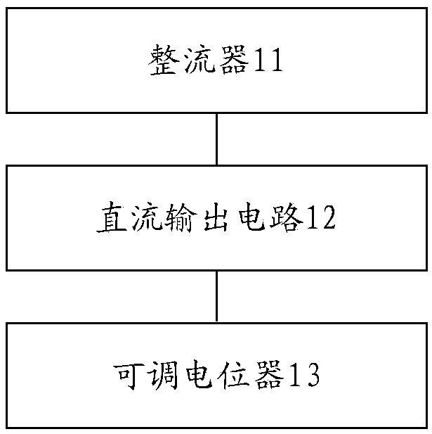
[0031] figure 1 Is a schematic diagram of a DC charging system according to an embodiment of the present invention, such as figure 1 As shown, the DC charging system includes: a rectifier 11, a DC output circuit 12, and an adjustable potentiometer 13, among which,
[0032] The rectifier 11 is used to convert the input AC power into DC power.
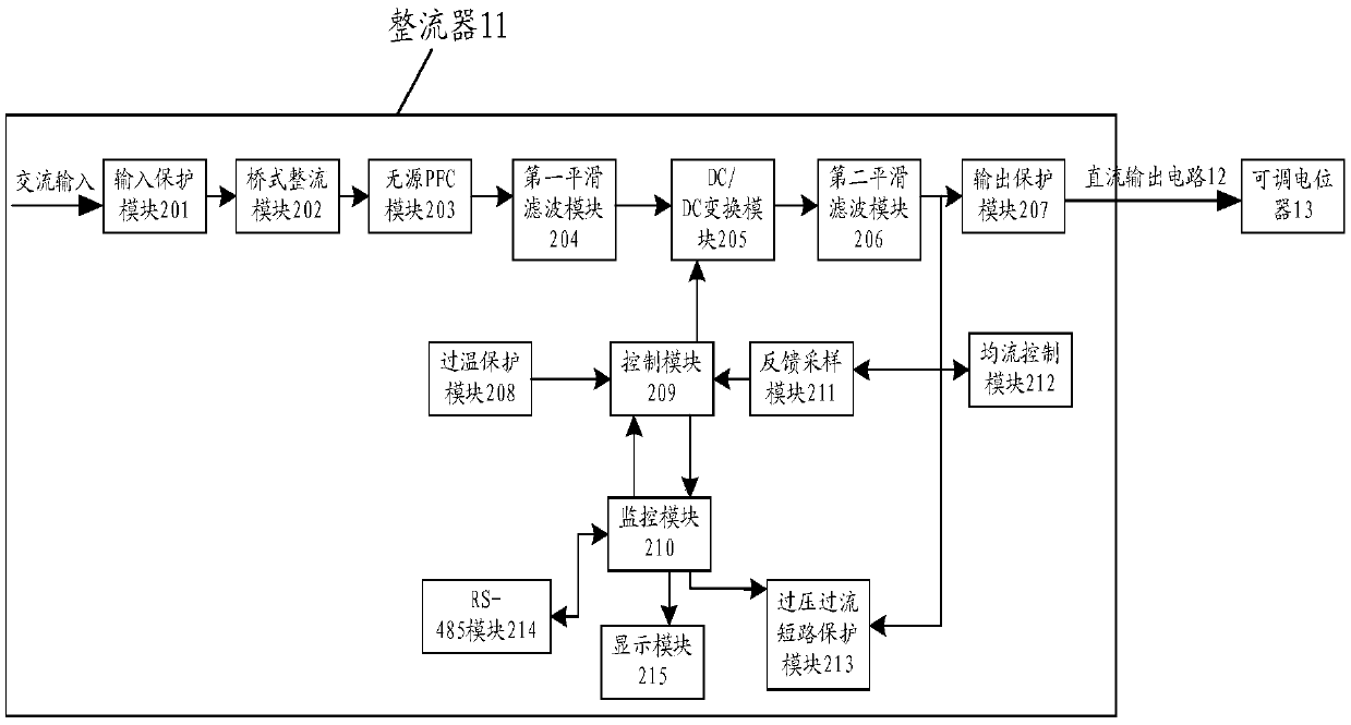
[0033] Among them, the rectifier includes: an input protection module for lightning protection and electromagnetic filtering of the input AC power; a bridge rectifier for converting the AC power after lightning protection and electromagnetic filtering into DC power.
[0034] Optionally, the input AC power can be three-phase AC power. Through the above-mentioned input protection module, the input three-phase AC power can be subjected to lightning protection treatment and electromagnetic filtering treatment, that is, EMI filtering treatment can be performed, and this part of the circuit can effectively absorb Lightning residual voltage or grid sp...
Embodiment 2
[0051] According to an embodiment of the present invention, an embodiment of a DC charging method is provided. It should be noted that the steps shown in the flowchart of the figure can be executed in a computer system such as a set of computer-executable instructions, and, although in The logical sequence is shown in the flowchart, but in some cases, the steps shown or described may be performed in a different order than here. Among them, the following DC charging method can be applied to the above DC charging system.
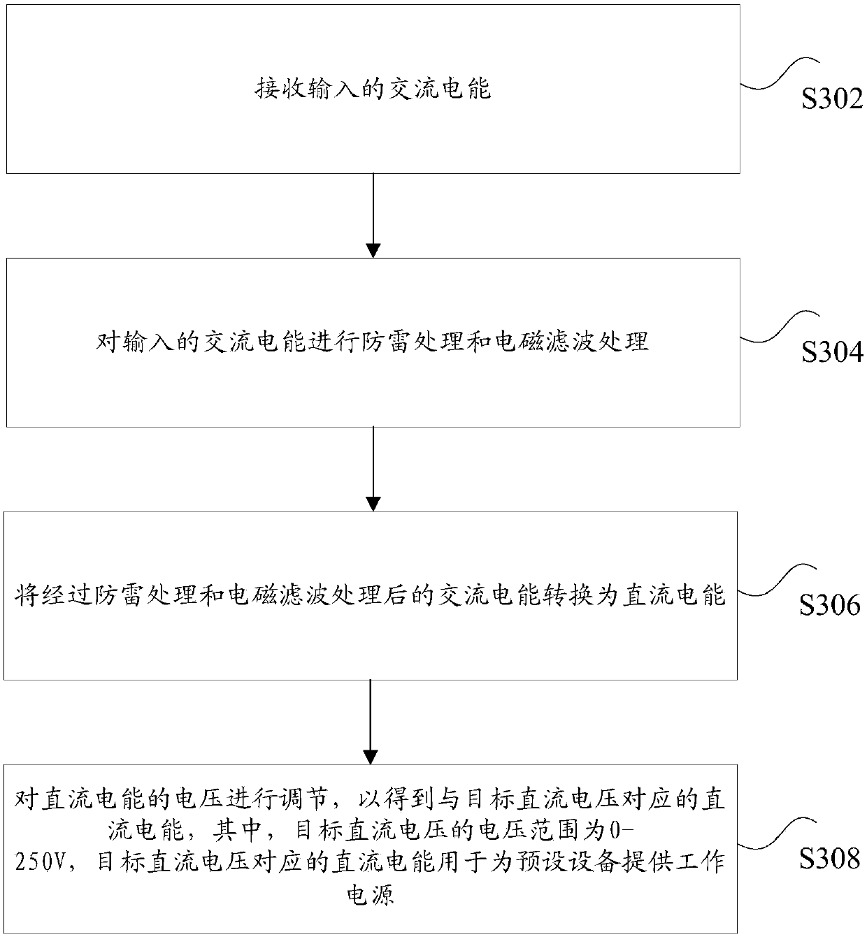
[0052] image 3 Is a flowchart of an optional DC charging method according to an embodiment of the present invention, such as image 3 As shown, the method includes the following steps:
[0053] Step S302: Receive the input AC power.
[0054] Step S304: Perform lightning protection processing and electromagnetic filtering processing on the input AC power.
[0055] Step S306: Convert the AC power that has undergone lightning protection processing and electromagnetic f...
Embodiment 3
[0059] Another embodiment is introduced below. In the DC charging device in the following embodiment, the operation of each module of the DC charging device may correspond to the steps in the above DC charging method.
[0060] Figure 4 Is a schematic diagram of an optional DC charging device according to an embodiment of the present invention, such as Figure 4 As shown, the DC charging device may include: a receiving unit 41, a processing unit 42, a conversion unit 43, and an adjustment unit 44, wherein,
[0061] The receiving unit 41 is used to receive the input AC power.
[0062] The processing unit 42 is configured to perform lightning protection processing and electromagnetic filtering processing on the input AC power.
[0063] The conversion unit 43 is used for converting the AC electric energy after lightning protection treatment and electromagnetic filtering treatment into DC electric energy.
[0064] The adjustment unit 44 is used to adjust the voltage of the DC power to obt...
PUM
 Abstract
Description
Claims
Application Information
 - R&D Engineer
- R&D Manager
- IP Professional
- Industry Leading Data Capabilities
- Powerful AI technology
- Patent DNA Extraction
Browse by: Latest US Patents, China's latest patents, Technical Efficacy Thesaurus, Application Domain, Technology Topic, Popular Technical Reports.
© 2024 PatSnap. All rights reserved.Legal|Privacy policy|Modern Slavery Act Transparency Statement|Sitemap|About US| Contact US: help@patsnap.com