
AR display device and wearable AR device

A technology for a display device and a projection device, which is applied in the directions of optics, instruments, optical components, etc., can solve the problems of insufficient compactness, heavy weight, and small exit pupil distance.

Active Publication Date: 2018-10-19
BEIJING UNICORN TECH CO LTD
View PDF14 Cites 13 Cited by
  • Summary
  • Abstract
  • Description
  • Claims
  • Application Information

AI Technical Summary

Problems solved by technology

[0006] First, due to the low degree of device reuse, the optical display module is large or heavy and not compact enough;
[0007] Second, the optical structure is too simple, and there are too few design parameters that can provide design freedom, so the imaging quality is low; the field of view is small, generally 30°-45°; the exit pupil diameter is too small, generally 6mm-10mm; The interpupillary distance is too small, generally 10mm to 14mm;
[0008] Third, some devices are difficult to manufacture, or some components are difficult to assemble, which is not conducive to mass production

Method used


Image

  • AR display device and wearable AR device
  • AR display device and wearable AR device
  • AR display device and wearable AR device

Examples


Embodiment 1

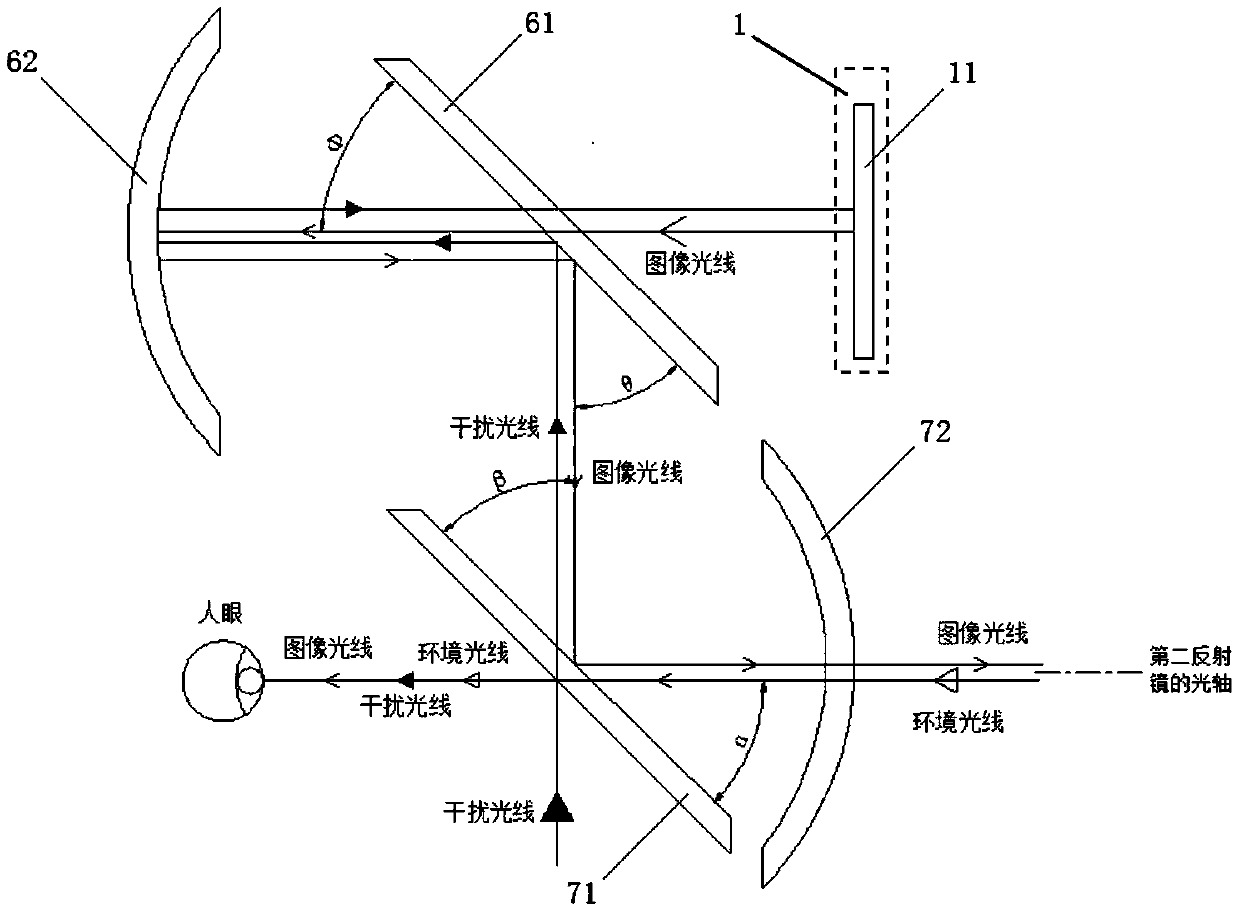
[0121] This embodiment provides an AR display device, such as image 3 As shown, the AR display device includes an image projection device 1 and an optical display module.

[0122] The image projection device 1 includes an image source 11 . The function of the image source 11 is to display images that need to be projected into human eyes. The image source 11 can adopt a planar image source with an integrated light source, for example, OLED (Organic Light-Emitting Diode, organic light-emitting diode), LCD (Liquid Crystal Display, liquid crystal display ) and other electronic devices that show the principle.

[0123] The optical display module includes a first beam splitter 61 , a first reflector 62 , a second beam splitter 71 and a second reflector 72 . The light sent by the image source 11 is sent to the first reflector 62 through the first beam splitter 61, is reflected back to the first beam splitter 61 by the first reflector 62, and then is sent to the second beam splitte...

Embodiment 2

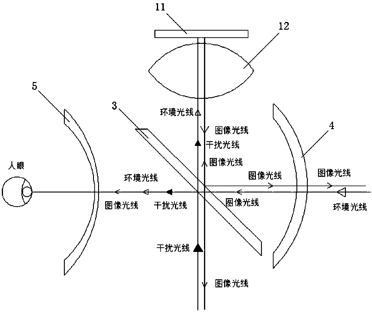
[0136] This embodiment provides an AR display device, such as Figure 4 and Figure 5 As shown, the AR display device includes an image projection device 1 and an optical display module.

[0137] The image projection device 1 includes an image source 11 . The optical display module includes a first beam splitter 61 , a first reflector 62 , a second beam splitter 71 and a second reflector 72 .

[0138] Figure 4 In the shown AR display device, the second reflector 72 is located below the second beam splitter 71, and the second reflector 72 may be a curved reflector because it does not block ambient light. Ambient light can enter human eyes through the second beam splitter 72 . This structure can double the utilization efficiency of image source light, and at the same time, the transmittance of ambient light can also be doubled.

[0139] Figure 4The shown AR display device works as follows:

[0140] A part of the image light emitted by the image source 11 can pass throug...

Embodiment 3

[0145] The AR display device provided in this embodiment is as Figure 6 As shown, it includes an image projection device 1 and an optical display module. Wherein, the optical display module includes a first beam splitter 61 , a first wave plate assembly 63 , a first mirror 62 , a second beam splitter 71 , a second wave plate assembly 73 and a second mirror 72 .

[0146] The first beam splitter 61 is a flat polarized beam splitter. The plate polarizing beam splitter may only include a polarizing beam splitting film (hereinafter referred to as the first polarizing beam splitting film), and may also include the first polarizing beam splitting film and the plate beam splitting mirror substrate. The first polarization splitting film is used to pass the polarized light whose polarization state is in the first direction, and reflect the polarized light whose polarization state is in the second direction. Wherein, the first direction and the second direction are perpendicular to ea...


PUM


Abstract

The invention provides an AR display device and a wearable AR device, belonging to the technical field of augmented reality imaging. An optical display module of the AR display device converges and images light rays through two times of reflection. The correct aberration ability of the optical display module is far greater than a refractive surface and the optical display module has the advantageof not causing chromatic aberration, thus overcoming the defects of a conventional optical system that chromatic aberration tends to exist by using refraction and the optical system is large in size and heavy in weight because the number of lenses is increased for compensation and correction. Meanwhile, with the increased number of components, clearer images, the larger field of view, a larger eyebox and a larger exit pupil distance can be obtained, and the size, weight and complexity of a system are reduced. An optical path of the optical display module is of a coaxial structure, and comparedwith an off-axis structure, the coaxial structure enables optical aberration to be evaluated and corrected more easily and optical components to be processed and manufactured more easily. In this way, the optical display module is easier to manufacture and assemble, batch production can be realized more easily, and the production cost is lower.

Description

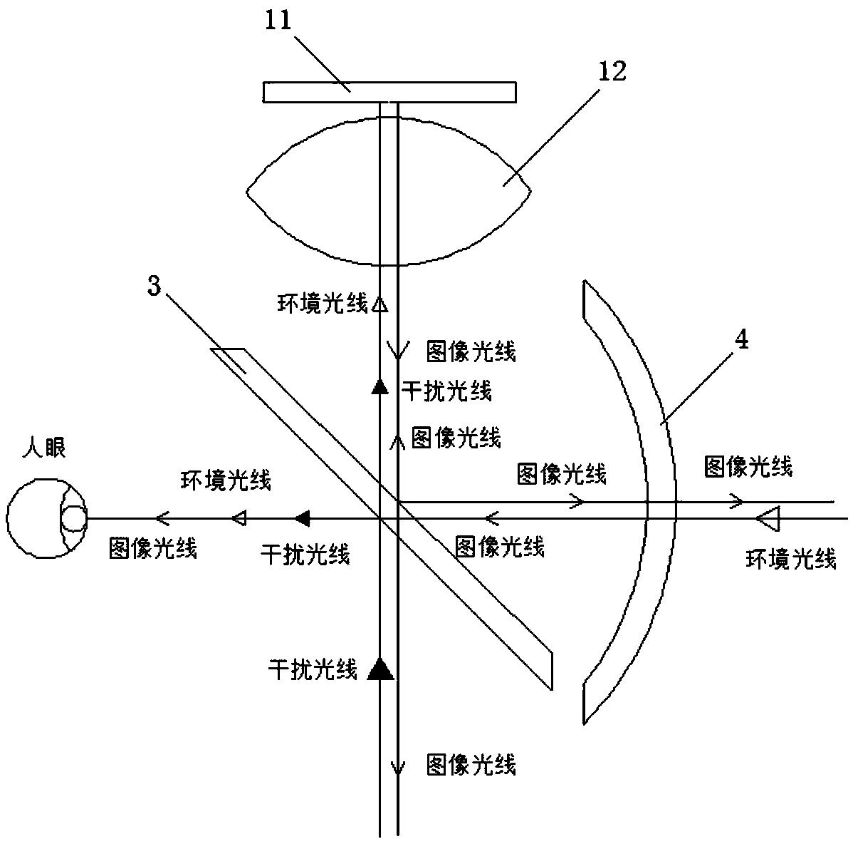
technical field [0001] The present invention relates to the technical field of augmented reality imaging, in particular to an AR display device and a wearable AR device. Background technique [0002] AR (Augmented Reality, Augmented Reality) is also known as mixed reality. Its principle is to apply virtual information to the real world through computer technology. The real environment and virtual objects are superimposed on the same picture or space in real time. [0003] Currently, people can interact with the real world through wearable devices, such as AR glasses or AR helmets. Such as figure 1 A schematic structural diagram of an AR display device in an existing AR glasses or an AR helmet is shown, as shown in figure 1 As shown, the existing AR display device optical system includes an image source 11, a beam splitter 3, a curved half mirror 4 and a lens 12 positioned above the beam splitter 3, the image source 11 is arranged on the upper part of the optical system, an...

Claims


Application Information

Patent Timeline
IPC IPC(8): G02B27/01
CPCG02B27/0101G02B27/0172G02B2027/0114G02B2027/0178G02B5/10G02B2027/0123G02B27/283G02B27/0955G02B27/0994G02B27/144G02B2027/0118
Inventor 肖冰梁晓斌徐驰
Owner BEIJING UNICORN TECH CO LTD
Learn More