Self-generating electricity air blowing mechanism for outdoor heater

A self-generating and heating technology, which is applied to generators/motors, electrical components, space heating and ventilation, etc., can solve the problems of poor heating effect of radiant gas heaters, inconvenient field operations, and high heater temperature , to achieve good outdoor heating effect, stable and uniform combustion flame, and sufficient combustion effect

Pending Publication Date: 2018-10-19
慈溪市恒进电子有限公司
View PDF0 Cites 3 Cited by
  • Summary
  • Abstract
  • Description
  • Claims
  • Application Information

AI Technical Summary

Problems solved by technology

Gas heaters are generally small in size, but they will produce smell, so they are generally used in places where it is not convenient to work in the field
[0003] When used outdoors, radiant gas heaters are generally used, but due to the special circumstances outdoors, the site is wide and the wind direction is uncertain, it is impossible to form a convection effect to transport heat to a specific area, so the heating effect of radiant gas heaters is not good. The loss of heat is huge, and the energy efficiency is very low. At the same time, due to the lack of convection, the local temperature of the heater will be high, and there are safety hazards such as fire.

Method used


Image

  • Self-generating electricity air blowing mechanism for outdoor heater
  • Self-generating electricity air blowing mechanism for outdoor heater
  • Self-generating electricity air blowing mechanism for outdoor heater

Examples


Embodiment Construction

[0028] The present invention will be described in further detail below in conjunction with the accompanying drawings and specific embodiments.

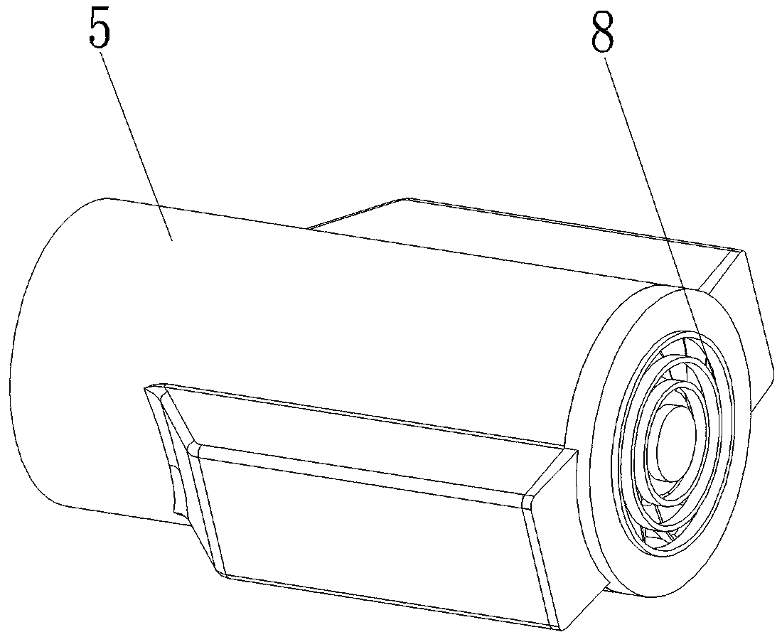
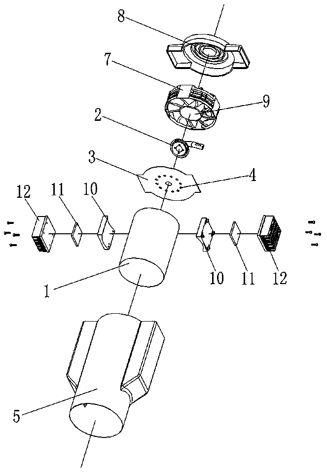
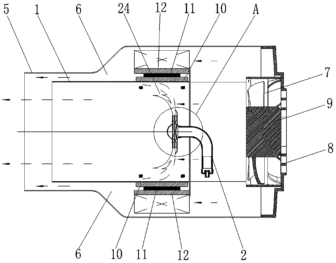
[0029] refer to Figure 1 to Figure 5 A self-generating and blowing mechanism for an outdoor heater, comprising a combustion cylinder 1, a combustion head 2 disposed in the combustion cylinder 1, an ignition device disposed in the combustion cylinder 1 and opposite to the combustion head 2, and further comprising:

[0030] The air distribution plate 3 is located at the rear end of the combustion tube 1, and several air holes 4 are opened on the air distribution plate 3;

[0031] Cooling cylinder 5, the combustion cylinder 1 is arranged in the cooling cylinder 5, the gap between the combustion cylinder 1 and the cooling cylinder 5 forms a cooling air passage 6, and the cooling cylinder 5 is provided with a air grille;

[0032] The fan 7 is used to supply air to the cooling duct 6 and the combustion tube 1, and is located at the rear ...


PUM


Abstract

The invention provides a self-generating electricity air blowing mechanism for an outdoor heater. The self-generating electricity air blowing mechanism comprises a combustion barrel, a combustion headarranged inside the combustion barrel and an ignition device which is arranged inside the combustion barrel and opposite to the combustion head and further comprises an air distribution plate, a cooling barrel, an air fan, a motor and a self-generating electricity component, wherein the air distribution plate is located at the rear end of the combustion barrel; the combustion barrel is arranged inside the cooling barrel, and the gap between the combustion barrel and the cooling barrel forms a cooling air passage; the air fan is used for supplying air to the cooling air passage and the combustion barrel; the motor is in transmission connection with the air fan; and the self-generating electricity component comprises heat conduction blocks, temperature difference electricity generating pieces and heat dissipation devices, the heat conduction blocks are used for conducting heat, the temperature difference electricity generating pieces are attached to the corresponding heat conduction blocks and are in electric connection with the motor, and the heat dissipation devices are used for performing heat dissipation and cooling on one end surfaces of the temperature difference electricity generating pieces. The self-generating electricity air blowing mechanism for the outdoor heater is simple and reasonable in structure and convenient and fast to use, the outdoor heater is made to havethe self-generating electricity function, running of the motor and the air fan can be realized, thus the heat inside the combustion barrel is transferred outwards, the convection effect is realized, so that the better outdoor heating effect is obtained.

Description

technical field [0001] The invention relates to the field of outdoor heaters, in particular to a self-generating blower mechanism of an outdoor heater. Background technique [0002] The most common heaters are electric heaters and gas heaters. It is mainly used in places that do not require high heating. The power supply uses 220V mains voltage, which is convenient, safe and environmentally friendly, but the effect is not very large, so it is not suitable for outdoor use. The gas heater is generally small in size, but it will produce smell, so it is generally used when it is not convenient for field work. [0003] When used outdoors, radiant gas heaters are generally used, but due to the special circumstances outdoors, the site is wide and the wind direction is uncertain, it is impossible to form a convection effect to transport heat to a specific area, so the heating effect of radiant gas heaters is not good. The loss of heat is huge, and the energy efficiency is very low...

Claims


Application Information

Patent Timeline
IPC IPC(8): F24D15/02F24C1/16H02N11/00
CPCH02N11/002F24C1/16F24D15/02
Inventor 陆旭
Owner 慈溪市恒进电子有限公司
Why Eureka
Try Eureka