Curved claw rotor of claw type vacuum pump and molded line design method thereof

A technology of vacuum pumps and rotors, applied in the direction of rotary piston pumps, pumps, calculations, etc., can solve problems such as wear, lower efficiency of claw vacuum pumps, and uneven meshing range

Pending Publication Date: 2018-10-19
CHINA UNIV OF PETROLEUM (EAST CHINA)
View PDF1 Cites 5 Cited by
  • Summary
  • Abstract
  • Description
  • Claims
  • Application Information

AI Technical Summary

Problems solved by technology

[0003] The profile line and meshing performance of the claw rotor directly determine the performance of the claw vacuum pump. The common profile line of the claw rotor is composed of 3 cycloids and 3 arcs. There are 4 sharp points in the rotor profile, which is easy to It will lead to wear, deformation and stress concentration at the sharp point, and there will be a great leakage hidden danger when the point and the cycloid mesh; A fully smooth claw-type rotor, the rotor profile consists of 6 segments of arcs, 2 segments of equidistant curves of long epicycloids and 1 segment of equidistant curves of short epicycloids. The smooth connection without sharp points improves the sealing performance, mechanical properties and meshing performance of the rotor; however, when the pair of claw rotors mesh with each other, due to the existence of the clearance volume, the efficiency of the claw vacuum pump is reduced. At the same time, Although the sharp point is replaced by the rear claw tip arc at the top of the claw, the engagement range is still not flat enough, and the engagement line is short, which will still cause a certain degree of wear

Method used


Image

  • Curved claw rotor of claw type vacuum pump and molded line design method thereof
  • Curved claw rotor of claw type vacuum pump and molded line design method thereof
  • Curved claw rotor of claw type vacuum pump and molded line design method thereof

Examples


Embodiment Construction

[0070] The present invention will be further described below in conjunction with the accompanying drawings and embodiments.

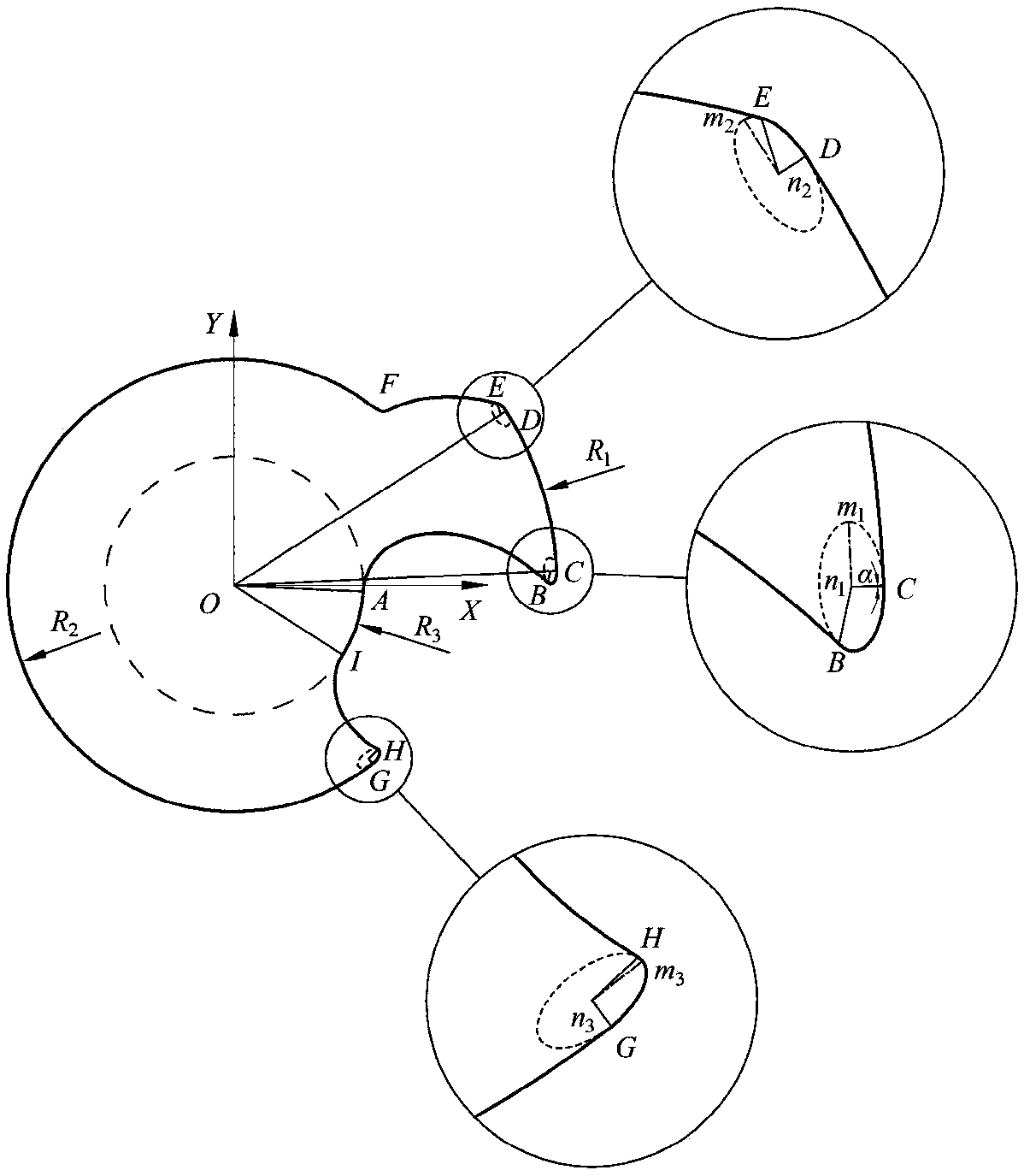
[0071] Such as figure 1 Shown is the profile diagram of the claw rotor of a proposed claw vacuum pump. According to the counterclockwise direction, the rotor profiles are: the first elliptical arc envelope line AB, the first elliptical arc BC, and the claw top circle Arc CD, second elliptical arc DE, third elliptical arc envelope EF, pitch circle arc FG, third elliptical arc GH, second elliptical arc envelope HI and claw bottom arc IA; between adjacent curves All smooth connections, no non-smooth connection points; the mechanical properties, meshing performance and sealing performance of the claw rotor are improved.

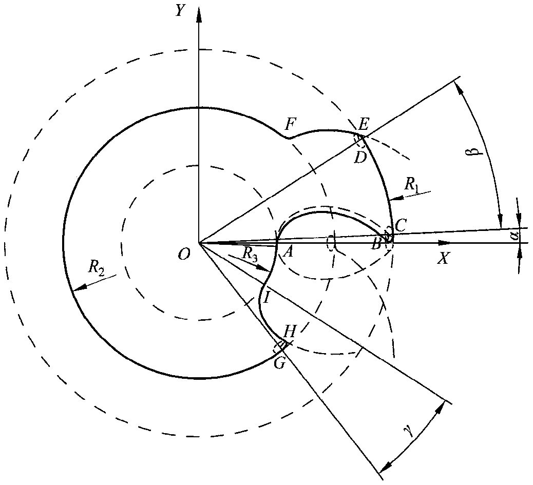
[0072] Such as figure 2 As shown, it is the profile line generation diagram of the left rotor of the claw rotor of a claw vacuum pump proposed, and the rotor profile generation method is as follows:

[0073] 1) Take the origin O as the...


PUM


Abstract

The invention discloses a curved claw rotor of a claw type vacuum pump and a molded line design method thereof. The rotor is composed of nine curved lines: three circular arcs, three elliptic arcs andthree elliptic arc envelope lines. Molded lines are constructed at the top, tip and bottom of the claw of the rotor by adopting the elliptic arcs and the elliptic arc envelope lines. Two rotors engaged to each other are totally same and the molded lines can be correctly engaged; adjacent curved lines are smoothly connected without unsmooth connecting points, so that the mechanical property, the engaging property and the sealing property of the curved claw rotor are improved. The rotor has a smaller clearance volume, the compression power consumption is reduced effectively, and the compressionratio of the claw type vacuum pump is improved. The tip of the claw of the rotor is more flat, large in engaging range and long in engaging line, so that wear is further reduced; the rotor is small in area, and the pumping speed and the volume utilization ratio of the vacuum pump are improved; the types of the molded lines of the claw type rotor are enriched according to the rotor, and the rotoris of important significance to development of the claw type vacuum pump.

Description

technical field [0001] The invention relates to a claw vacuum pump, in particular to a claw rotor of the claw vacuum pump and a design method thereof. Background technique [0002] The claw vacuum pump is a dry vacuum pump widely used in petrochemical, pharmaceutical, and food fields. It has the advantages of simple structure, stable operation, and low noise; the claw rotor is the core component of the claw vacuum pump, and the claw rotor It is composed of a pair of rotors that can realize conjugate meshing. The synchronous and opposite double-rotation motion of the rotors is realized through the synchronous gears, so as to realize the periodic change of the volume of the working chamber, complete the suction, compression and discharge process of the gas, and achieve the purpose of continuous vacuuming . [0003] The profile line and meshing performance of the claw rotor directly determine the performance of the claw vacuum pump. The common profile line of the claw rotor is...

Claims


Application Information

Patent Timeline
IPC IPC(8): F04C25/02F04C18/12G06F17/50
CPCF04C18/123F04C25/02G06F30/17
Inventor 王君冯浩志魏蜀红李宏鑫沙润东崔淑洁陈志凯
Owner CHINA UNIV OF PETROLEUM (EAST CHINA)
Why Eureka
Try Eureka