Floating boring tool structure for inner wall of steel tube

A steel pipe inner wall and boring tool technology, applied in the direction of tool holders, etc., can solve the problems of poor processing accuracy and processing efficiency, poor processing accuracy of the steel pipe inner wall, troublesome disassembly, etc., to improve processing accuracy and processing efficiency, improve processing Accuracy and processing efficiency, the effect of not easy to break the knife

Inactive Publication Date: 2018-10-19
惠州市豪美仕智能技术有限公司
View PDF7 Cites 3 Cited by
  • Summary
  • Abstract
  • Description
  • Claims
  • Application Information

AI Technical Summary

Problems solved by technology

[0005] The object of the present invention is to provide a floating boring tool structure on the inner wall of a steel pipe to solve the problems in the above-mentioned background technology that due to the relatively rough inner wall of the steel tube or a certain jumping range of the steel tube during processing, ordinary fixed boring tools are prone to breakouts. Or the machining accuracy of the inner wall of the steel pipe is poor, and the existing floating boring tool also has too complicated structural design, which leads to troublesome disassembly during maintenance and replacement, and problems and deficiencies such as the inability to improve machining accuracy and machining efficiency.

Method used


Image

  • Floating boring tool structure for inner wall of steel tube
  • Floating boring tool structure for inner wall of steel tube
  • Floating boring tool structure for inner wall of steel tube

Examples


Embodiment approach

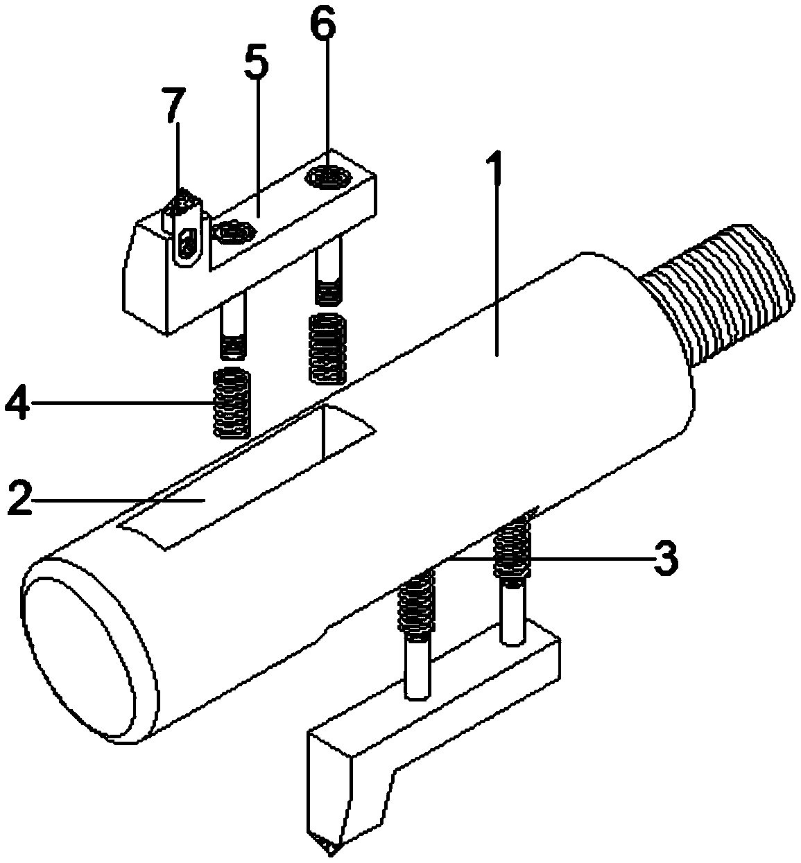
[0033] A steel pipe inner wall floating boring tool structure, including: tool bar 1, first tool slot 2, second tool slot 3, spring 4, tool seat 5, half shaft bolt 6, tool head 7, extension rod 8, taper handle 9 , cutter head groove 501; the first cutter groove 2 is located at the upper inner position of the cutter rod 1, and the first cutter groove 2 and the cutter rod 1 are integrated; the second cutter groove 3 is located at the lower inner position of the cutter rod 1 , and the second sipe 3 is integrated with the knife bar 1; the spring 4 is respectively installed inside the first sipe 2 and the second sipe 3, and the spring 4 is connected to the first sipe 2 and the second sipe 3 Through the half-axis bolt 6; the tool seat 5 is respectively installed inside the first sipe 2 and the second sipe 3, and the knife seat 5 and the first sipe 2 and the second sipe 3 are penetrated by the half-axis bolt 6. connected; half-shaft bolts 6 are respectively installed inside the first...


PUM


Abstract

The invention provides a floating boring tool structure for the inner wall of a steel tube. The floating boring tool structure comprises a tool bar, a first tool groove and a second tool groove. The first tool groove is formed inside the portion above the tool bar, and the first tool groove and the tool bar are of an integrated structure. The second tool groove is formed inside the portion below the tool bar, and the second tool groove and the tool bar are of an integrated structure. Springs are mounted inside the first tool groove and the second tool groove and connected with the first tool groove and the second tool groove in a penetrating manner through half-shaft bolts correspondingly. Tool aprons are mounted inside the first tool groove and the second tool groove and connected with the first tool groove and the second tool groove in a penetrating manner through half-shaft bolts correspondingly. The floating boring tool structure is structurally improved, therefore, the structure has the advantages that tools are not likely to be broken, the structure is convenient to dismount when being replaced for repair, the rough machining and finish machining integrated operation functionis achieved, and machining precision and machining efficiency are improved; and thus, problems in the background art are effective solved, and defects in the background art are effectively overcome.

Description

technical field [0001] The invention relates to the technical field of boring cutters, in particular to a floating boring cutter structure for processing the inner wall of a steel pipe. Background technique [0002] In the mechanical processing of steel pipe products, it is often necessary to derust or expand the inner wall of the steel pipe so that it can meet the requirements of the use. This processing process needs to be completed with the help of a boring machine, so the boring tool used to process the inner wall of the steel pipe on the boring machine plays a very important role. [0003] However, because the inner wall of the steel pipe is relatively rough or there is a certain beating range of the steel pipe during processing, the ordinary fixed boring tool is prone to breakout or the machining accuracy of the inner wall of the steel pipe is poor, and the existing floating boring tool also has structural design problems. It is too complicated, which leads to more tr...

Claims


Application Information

Patent Timeline
Patent Type & Authority Applications(China)
IPC IPC(8): B23B29/24
CPCB23B29/24
Inventor 黎志瀛
Owner 惠州市豪美仕智能技术有限公司
Why Eureka
Try Eureka